Domain Architecture
Table of Contents
At the centre of MASD lies its domain architecture. The present chapter builds upon the backdrop sketched by the Modeling Conventions section and provides a comprehensive picture of its motivation, core entities and associations.1 The chapter first discusses the three individual domains that make up the domain architecture: the physical domain (the Physical Domain section), the logical domain (the Logical Domain section) and the variability domain (the Variability Domain section). The LPS section then concludes the chapter by bringing these three domains together to form the Logical-Physical Space (LPS).
Before entering the analysis proper, a word is warranted with respect to the
descriptions and figures employed within. These are not intended as formal
models but are instead at a higher level of abstraction, and should be
understood as exemplary cartoons, freely mixing architectural levels as
necessary — e.g., metamodels, models
and object instances may be combined on the same plane, if doing so makes an
explanation more accessible.2 Secondly, a note on
typography: a constant width font is used to highlight terms of
MASD's ubiquitous language.3
With that in mind, let us enter the first and most important domain within MASD.
Physical Domain
The physical domain is the subset of MASD's problem domain comprised of physical artefacts, as depicted by Figure 1, and it is predictably dominated by file artefacts and folder artefacts. Prior to analysing these entities in detail, one must first describe the processes that led to the present state of affairs, in terms of physical analysis and design (the Physical Analysis and Design section), physical modeling (the Physical Modeling section) and, subsequently, by characterising its relationship with input variability (the Function Variability section). The remaining subsections will then cover in detail each of the core physical elements and their associations (the Artefacts section through the Platforms and Cartridges section).
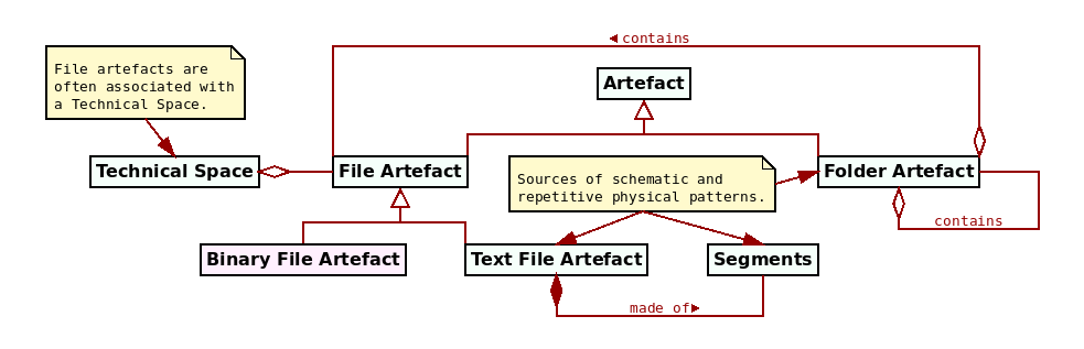
Figure 1: Key entities in the physical domain.
Physical Analysis and Design
At a first glance, MASD's physical analysis and design appears to be a simple expression of Domain Engineering's Domain Analysis and Domain Design (Marco Craveiro, 2021) (Chapter 6), when applied to MASD's physical domain. However, since the shift in perspective caused by the "problem space / solution space inversion" adds significant complexity, it is important to understand the specificity of this application. Figure 2 helps in doing so by portraying both in simplified form: on the left, we have Domain Analysis and Domain Design — often used in an MDE context — and, on the right, MASD's physical analysis and design. The two approaches are separated by a bold black line.
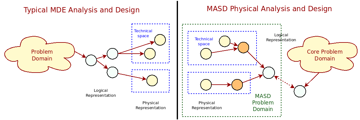
Figure 2: MDE analysis versus MASD physical analysis.
In the figure, yellow circles represent physical artefacts such as files and directories, clustered around dashed blue squares that denote individual TSs. For their part, light-blue circles represent logical elements such as classes and other high-level modeling constructs, likely in TS agnostic form. On the left side of the figure, one begins by observing a nebulous problem domain and designing a set of logical entities to form one or more models that fit requirements. Those logical entities will ultimately give rise to concrete physical entities through refinement, although these are often viewed as mere by-products of the process.4
In contrast, the right-hand side of the picture reflects MASD's call for the reversal of this approach: physical entities themselves become the problem domain and one arrives at their logical representation, denoted by orange circles, through empirical analysis, with the core problem domain losing relevance in the process (far right).5 Though perhaps not clear from the diagram, MASD's emphasis is on a comparative analysis of physical elements across TSs, not on the metamodels associated with each TS. It is so because MASD's analysis is driven by empirical evidence within the physical domain, rather than by the logical entities and meta-entities that inhabit each TS — even if the latter is more in keeping with MDE's ethos of metamodel to metamodel transforms (Marco Craveiro, 2021) (Chapter 3).6
A consequence of this favouring of empirical evidence is that physical analysis and design became distinct from that of their traditional MDE counterparts, where discussions with stakeholders and UML diagrams from a business viewpoint abound.7 In contrast, their application within MASD is closer, at least in spirit, to the modeling of scientific objects such as neurons, which were inspirational.8 Since the object of our study are Schematic and Repetitive Patterns in the Physical space (SRPPs), we opted for designing a specific approach for their handling which combines physical analysis and design into a single process, described next.9
Physical Modeling Process
The first challenge in modeling SRPPs is in defining their nature. As already alluded to in The MASD Methodology, SRPPs are conceptually close to Stahl et al.'s schematic and repetitive code; however, physical patterns were preferred over code so as to bring clarity to our ubiquitous language. Whilst source code is MASD's primary target — it is, by definition, the central artefact type in a conventional software product — the methodology aims to model any physical entity manifesting schematic and repetitive patterns, making the new nomenclature a better reflection of these broader aspirations.10
Terminology aside, an open question remained on what was meant precisely by the term, so placing the concept on firmer ground was a priority. We did so by stating three axioms upon which all our analysis was to rest. First, ascertaining what is "schematic and repetitive" was declared to be a subjective matter, relative to many qualitative factors such as the experience of the observer, and thus demanding extensional definitions.11, 12
Secondly, regardless of their subjective nature, we decided that:
- not all physical entities have patterns, nor are all patterns schematic and repetitive; these we deemed to lay largely beyond the scope of MASD.13
- a physical entity may be partially composed of schematic and repetitive patterns, and thus only partially under the remit of MASD (cf. the Relations section).
Thirdly, and most significantly, we equated the discovery of physical entities with schematic and repetitive patterns to the modeling of physical entities at a level of detail sufficient for their reproduction. In other words, one determines if a physical pattern is schematic and repetitive by reproducing it by automated means; if it is possible to do so, then a pattern is deemed to be an SRPP.
What follows from these axioms is that an empirical process of discovery is needed in order to uncover patterns of interest. To arrive at such process, ad-hoc experimentation was carried out on a number of artefacts from an initial set of projects, until reproduction was achieved. Reflecting on the endeavour, we identified a number of well-defined steps:
- Sampling: one must first determine the size of the physical sample, ensuring adequate coverage — e.g. across different TSs, possibly of different kinds, files of different types, and so forth.
- Decomposition (or Segmentation): each entity in the sample must be analysed in detail, and divided into well-defined constituent parts called segments.
- Labelling and Classification: the identified parts must be named and categorised by means of taxonomic and morphological analysis. These will give rise to models of the physical entities and their constituent parts.
- Reconstruction: the models are then used to recreate the original physical entity — for example via M2T transforms — at which point the pattern is declared to be a SRPP.
- Cataloguing and Parameterisation: finally, the model for the entity is placed in the broader context of the existing catalogue of patterns. Doing so may entail merging the functionality with existing entities, adding additional parameterisation to existing entities, and so on.
Whilst well-defined in theory, note that the modeling process laid out here is a generalisation of what happens in practice, for these steps are seldom applied in such a clear-cut manner. There often is an overlap between steps, as well as a need for continued iteration in order to obtain the best results. In addition, though our work incorporated all of these steps, several challenges were faced initially due to the ad-hoc nature of the approach, as we tried to gain a better understanding of its mechanics. Sampling proved to be particularly problematic. Firstly, our original sample was composed of two trivial C++ and C# projects — in software engineering parlance, "hello world" projects — but these evolved over time and ultimately become the MRI's C++ and C# reference products.14, 15 Secondly, the source code of the MRI code generator was also incorporated into our sample, even as it mutated drastically over time.16, 17 Clearly, a more disciplined experimental approach would have been beneficial, with a rigorous process for artefact selection and better care taken in managing artefact evolution.
A second type of challenge was in distinguishing between physical elements, models and their instances, since we initially referred to all using the same terms (i.e. files and directories). In order to avoid confusion between real files and directories, as found in a filesystem, and their representation within MASD, we decided to qualify MASD physical entities with artefact (e.g. file artefact, folder artefact). This terminology was incorporated into MASD's ubiquitous language and is used consistently throughout the present manuscript. In the same vein, though not often mentioned to avoid confusion, MASD's physical elements are still logical representations of concrete physical elements.
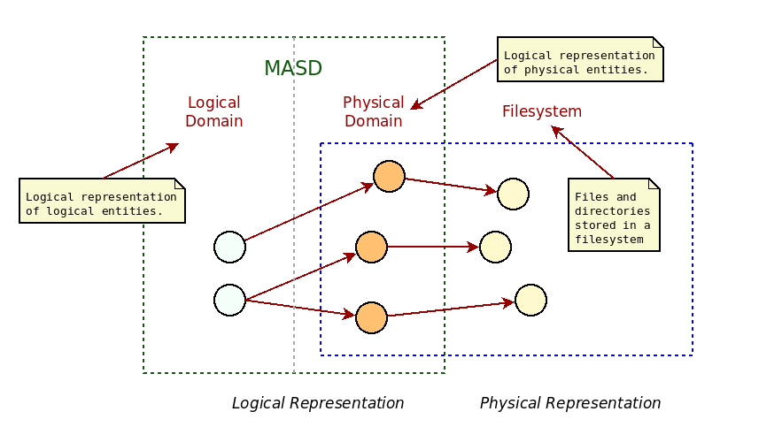
Figure 3: Transforms from logical representation to filesystem.
As Figure 3 should make clear, we are not referring to the logical dimension within MASD (the Logical Domain section), but instead to the modeling and subsequent refining of MASD's logical representation of physical entities into its final form, encompassed by the area of the dashed blue square in the picture. There, we take an instance of a physical model element (circles in orange) and create the corresponding file or folder in the filesystem (circles in yellow). Once the terminology was modified to reflect this, the ubiquitous language became unambiguous.
Regardless of challenges, the process has allowed us to identify and incorporate a number of physical patterns, many of which proved useful in the implementation of the MRI's code generator itself. What follows is a non-exhaustive list of SRPPs:
- type definitions, including constructors and properties (getters and setters);
- GoF design patterns (Vlissides, John and Helm, Richard and Johnson, Ralph and Gamma, Erich, 1995);
- serialisation support for different formats such as JSON and XML, possibly using different serialisation libraries;
- several mechanisms for test data generation;
- pretty-printing — i.e. dumping object state into a human-readable string representation;
- ORM mapping, providing RDBMS support;
- hashing — the generation of a hash function for the given state of an object;
- lexical casting, converting a C++ type into a string representation;
- unit test generation, validating the functionality of the generated features;
- generation of mocks for unit testing;
- and many more.
As more physical patterns were identified and implemented, further empirical evidence was accumulated on their general characteristics. Since the continued growth of the pattern catalogue is a key concern of the methodology, and given that reconstruction is not always feasible, distinguishing what is reconstructible from what is not became a central question to MASD. In order to better understand the commonalities between the patterns within the catalogue, we decided to classify them with regards to input variability18.
Taxonomy of Functions of Input Variability
A property common to the captured SRPPs is that they all are trivial functions of input variability. Somewhat tautologically, a trivial function of input variability is defined to be any physical entity that can be fully or partially reproduced, given arbitrary (but valid) input describing structural or non-structural variability.19 Reflecting on the modeling process (the Physical Modeling section), we realised that the steps of decomposition, labelling and classification are in effect an exercise in teasing apart functional dependencies on input variability from each physical entity, as explained by the flowchart in Figure 4.
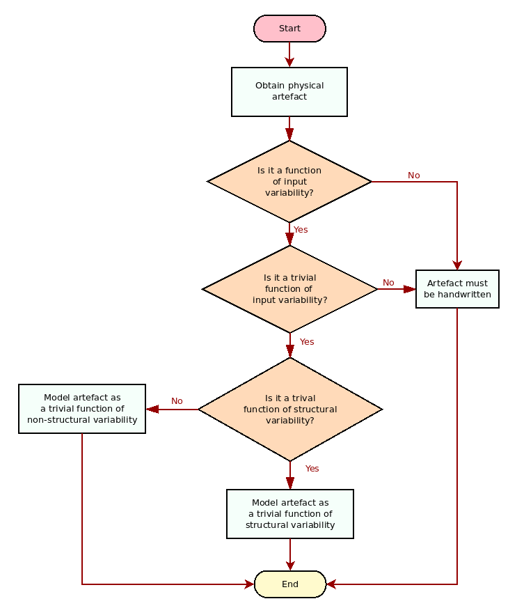
Figure 4: Physical elements and variability.
From this perspective, one can then create a taxonomy of the identified SRPPs with regards to input variability, leading us to Figure 5. Physical elements are first classified as dependent or independent of input variability. Any element which is independent of input variability is inherently not reproducible — for example, free text, arbitrary directory structures and the like — and thus ignored (marked in red). Next, physical elements which are functions of input variability can either be complex functions — that is, functions which cannot be described in a mechanical manner, and thus must be ignored — or they are trivial functions of input variability. As there are two kinds of input variability, there are also two kinds of trivial functions: trivial functions of structural variability and trivial functions of non-structural variability.20 Two sample trivial functions of non-structural variability are supplied: boilerplate and a long-form licence text such as the GNU Public Licence.21, 22 Finally, trivial functions of structural variability — which we often abbreviate to just trivial structural functions — are classified into two kinds, and several examples are provided for both.
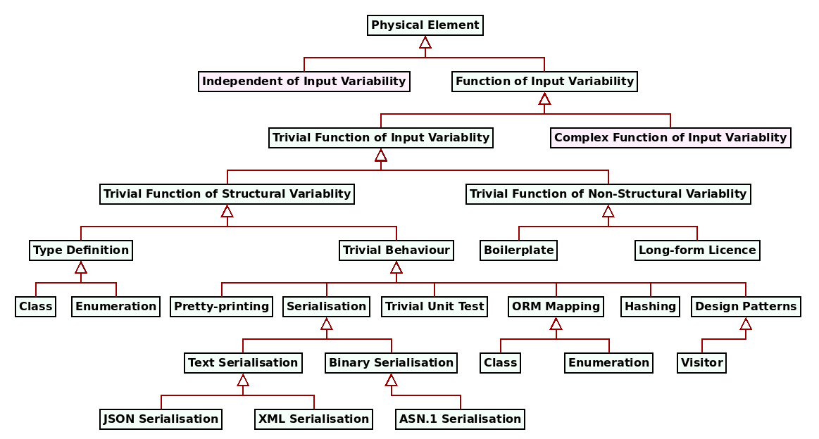
Figure 5: Taxonomy of physical elements with regards to variability.
Trivial structural functions have two main use cases. The first and most obvious
is the definition of data types — e.g., classes and their
attributes.23 The second use case is the implementation of
simple behaviours for those data structures which depend on structural
variability, such as serialisation and ORM support. These we refer to
as trivial behaviours, in contrast to complex behaviours which transcend
"simple mathematization" — to
borrow Hutchinson et al.'s wise words, out of context though they may be
(Hutchinson, John and Rouncefield, Mark and Whittle, Jon, 2011) — and thus demand manual handling. From this lens,
special purpose code generators (Marco Craveiro, 2021a) are seen to either
generate type definitions and a single trivial behaviour — e.g. protobuf
and the XSD tool generate the type definition and a serialisation
format — or solely a trivial behaviour — e.g. ODB generates the
ORM infrastructure, but relies on an existing type definition. With
SRPP, what MASD proposes is the inventorisation of all such
trivial behaviours and their unification under a single, integrated,
framework.24
Once a taxonomy for input variability functions had been arrived at, we then set on devising a scheme for their composition. The literature provided ample material in this regard, which was found to be inspirational but ultimately unsuitable for our needs.25 Using MASD's philosophy as a guide, we settled on a simple — and consequently inflexible — approach: a generated artefact may only be composed of zero or one trivial structural functions and zero or more trivial non-structural functions.26 Admittedly, the limitation is severe, but the trade-off removes most of the complexity inherent to composition, and is therefore in keeping with the methodology's goals.
The limitation is perhaps best understood by means of an example. In traditional
OO programs, objects accumulate different kinds of behaviours, in an
attempt to model entities found in the problem domain. Thus, it is common for a
class to contain both domain-specific behaviours — e.g. a Shape may be
able to Draw, Rotate and so forth — as well as infrastructural behaviours
— e.g. the Shape may also be able to
SerialiseToJson, ToString and the like. It is often the case that all of
these behaviours are implemented as methods in one file. The restrictions on
composition described above mean that MASD explicitly forbids such
behavioural composition with regards to infrastructure; each of these behaviours
— e.g. "JSON Serialisation", "Pretty-printing", etc. — is mapped to a
separate trivial structural function and is associated with a single file
artefact.27
Having embraced the unsophisticated approach, it was then straightforward to align generational variability with the specific use cases identified within the physical space:
- Positive variability was deemed to be best suited to modeling the inter-artefact composition of trivial structural functions. By making these responsible for separate artefacts, we greatly simplified the process of stitching together the final implementation — which now becomes a mere expression of artefact relations (the Artefacts section). In addition, non-structural variability can be used to configure the presence or absence of each top-level function, in turn determining artefact relations. Thus, whilst still a difficult problem, it opens the door to the application of solving (the Variability Domain section).
- Negative variability was deemed to be better suited to modeling intra-artefact instances of non-structural variability. For example, one can enable or disable class constructors as part of a type definition in a straightforward manner, adding little complexity to the overall process.
All of these moving parts can now be summarised into a cohesive narrative:
- MASD locates physical entities with SRPP by empirical means. Content is deemed to be a SRPP if a trivial function can be created that reconstructs the target.
- MTs (M2Ts in particular) are be used to implement trivial functions of input variability. These make use of negative variability techniques to handle non-structural variability.
- each generated artefact must have a single responsibility, and that responsibility imbues the artefact with a type within MASD's physical representation.28 The type is the trivial structural function.
- a broader framework is required to handle the inter-artefact composition of trivial functions of input variability, making use of positive variability techniques. As we shall see, MASD's solution is to embed the framework into the geometry of physical space itself (the Folders section).
File Artefacts
File artefacts in MASD are a generalisation of regular files as
defined by the POSIX specification (IEEE, 2018).29
They can be organised hierarchically using folder artefacts, a generalisation
of POSIX's directories which will be the subject of further scrutiny
in the Folder Artefacts section. The next three sections
demonstrate how physical modeling helped reveal the deep
structure30 within file artefacts by dissecting their taxonomy,
morphology and relationships.
Taxonomy
MASD divides file artefacts into two types, according to their
content encoding: text file artefacts and binary file artefacts (Figure
1). The latter are outside the methodology's present remit,
and hence marked in red in this and subsequent figures.
Encoding is a salient property of file artefacts, but it is only a starting
point for their taxonomy; Figure 6 provides an example of a
more detailed taxonomic view.
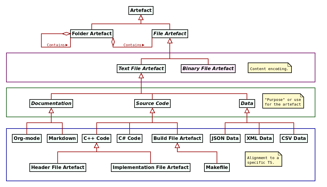
Figure 6: Example file taxonomy.
In this taxonomy, the green box contains three classes of file artefacts
according to their purpose: documentation, source code and data.
Conversely, the blue box consists of artefacts that are aligned with a specific
TS. For example, documentation is sub-divided into
org-mode31 and markdown32, two popular formats
used in FOSS projects. Source code has two sample programming
languages, C++ code and C# code. The C++
TS is of particular interest because it supports several distinct file
types. The figure depicts header file artefacts — typically used to declare
types and functions to be called elsewhere — and implementation file
artefacts; other types do exist within this TS, such as module
definitions, as per the latest revisions of the language
({ISO}, 2020).33, 34 Build file artefacts
were added to the diagram to demonstrate that not all source code is connected
with a programming language, with makefiles illustrating the kind of instances
to be found in this category. Finally, three data file artefacts are shown,
targetting JSON, XML and CSV representations.
One may infer from the above description that artefact classification is largely
mechanical, but the process proved more challenging in practice. Let us consider
the case of the Visual Studio35 IDE projects, where there are
at least two file types conveying project information: .csproj for C# projects
and .vcxproj for C++ projects. These files have been expressed in XML
for a number of releases, but later versions use JSON instead. In
either case, they could be plausibly classified as data or source code, so an amount of judgement is needed to
guide the decision making. Within MASD they were classified as build
file artefacts, because the internal representation was deemed less important
than the role they play on the development process. Similarly, it's also
debatable whether build file artefacts constitute source code or are a
separate category altogether, such as IaC. These and other questions
are grey areas in the classification process.
Morphology
Beyond taxonomy, physical modeling also interrogated the composition of file
artefacts by inspecting their internal structure. Using elements from the
before-mentioned sample projects, a morphology was constructed by dividing each
file into its constituent parts until atomic
segments were reached.36 The analysis greatly
benefited from our prior research on special purpose code generators
(Marco Craveiro, 2021a), because tools such as ODB had already identified
segments such as prologue and epilogue.
Figure 7 exemplifies the segmentation process by decomposing a
C++ enumeration header file into its fundamental parts, which shall now be
described. The file in question has three top-level segments: the prologue,
the body and the epilogue. The prologue and the
epilogue make up the boilerplate, thusly named because it has little
sensitivity to structural variability.37 The prologue is
composed of the following sections:
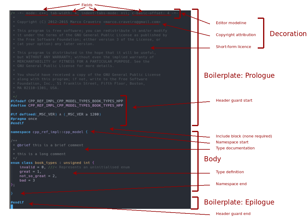
Figure 7: Morphology of a sample C++ file.
- the
decoration, so named because it mainly contains informational elements. It is made up of the following:- the
editor modeline, where editor-specific parameters are configured such as the spacing to use in Emacs or Vi, and variables of a similar ilk. Theeditor modelineis composed of astart marker, a set of key-value-pairs calledfields, aseparatorbetween them and anend marker. - the
copyright attribution, identifying the author or authors of the file. Thecopyright attributionis composed of zero or morecopyright attribution entries, each made up of adate range, acopyright holderand acopyright email address. - a
short-form licence, detailing the terms and conditions for the source code. Along-form licenceis also available, but it is a stand-alone file whereas theshort-form licenceis a file sub-component.
- the
- the
header guard, used by C++ to ensure a type is defined only on first inclusion, with subsequent mentions acting as no-ops.Header guardsare the first scoped segment, with a start and an end; the start is part of theprologuewhereas the end belongs to theepilogue. Also of significance is the fact that theheader guard nameis a function of structural variability — more specifically, ofnamespacecontainment.
Next we have the body, containing the core of the file and highly sensitive to
structural variability. The body in the figure is made up of:
- a
namespace, the second scoped segment within the file, with its own start and end. - the
type documentation, expressed in Doxygen notation.38 - the
type definition. Note that each individual entry within the enumeration can have its own documentation, if supplied. In the example, only theinvalidenumerator makes use of this feature. Significantly, note that the type definition is not a scoped segment in MASD because it is contiguous; that is, it does not contain other elements.
The file ends with the epilogue, in this particular case catering only for the
closing of the header guard. Variability does allow for
the editor modeline to be moved onto the prologue when requested, via
configuration, but this feature is not used by the example.
Absent from Figure 7's body is the include block, as the
enumeration does not depend on any other file.39 Since
include blocks are a significant element in MASD's support for the
C++ TS, a sample was sourced from elsewhere to demonstrate the concept
(Figure 8). The include block,
bounded by a red box in the picture, is typically located right after the
header guard's start. It is composed of a set of include directives, often
abbreviated to just includes, one of which is labelled in green. Include
directives contain the inclusion path for all files the current artefact
depends on, as exemplified in blue.
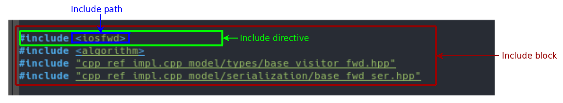
Figure 8: Example include block.
Include blocks were also chosen for this analysis because they demonstrate how
and why MASD departs from TS concepts. In this particular
case, the language of the ISO Standard was overridden because include paths
are a clearer statement of intent when compared to the standard's
wording.40 Similarly, the C and C++ programming language
specifications do not require the notion of a "block" — includes may be placed anywhere in a file, according to
language syntax — whereas MASD finds having a cohesive entity to
handle inclusion extremely helpful for its modeling and reconstruction needs. In
other words, MASD cares about the observed patterns of use rather than
the full universe of possibilities allowed by the TS metamodel.
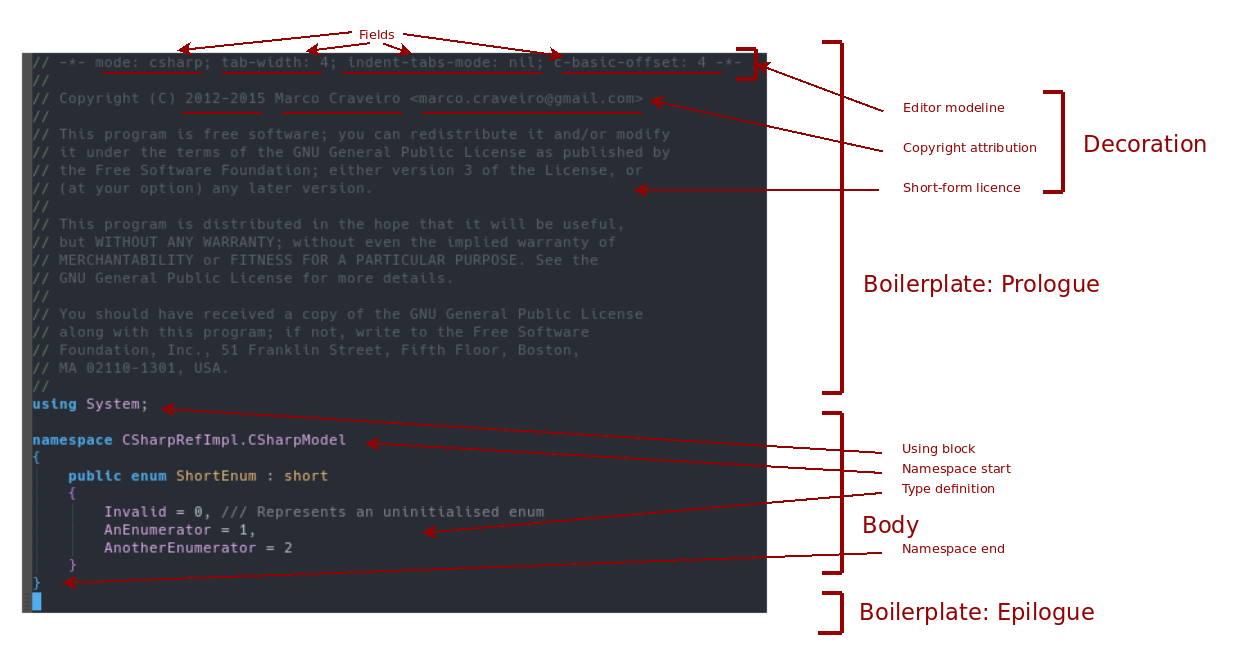
Figure 9: Morphology of a sample C# file.
For completeness, Figure 9 carries out a similar
morphological examination on an file from the C# TS, it too depicting
an enumeration. There are some noteworthy points, so a brief comparison between
figures is in order. Most of the elements are common to both Figure
7 and 9,
with a few notable exceptions. The boilerplate of Figure
9 is composed entirely of the decoration, for no other
elements are available to this TS, and the comment syntax used in the
decoration is shown to be sensitive to the TS.41
Within the body, the using block replaces the before-mentioned include
block in the latter figure, though performing a similar role.
Overall, a surprising degree of symmetry emerges between these two examples,
though they belong to two distinct TSs. To further the similarities,
one could — and indeed, MASD does — generalise
the include block and the using block into a
dependencies block, as shown in Figure 10 below. This
generalisation of relations was carried out as part of our third and final take
on file artefacts, discussed in the next section.
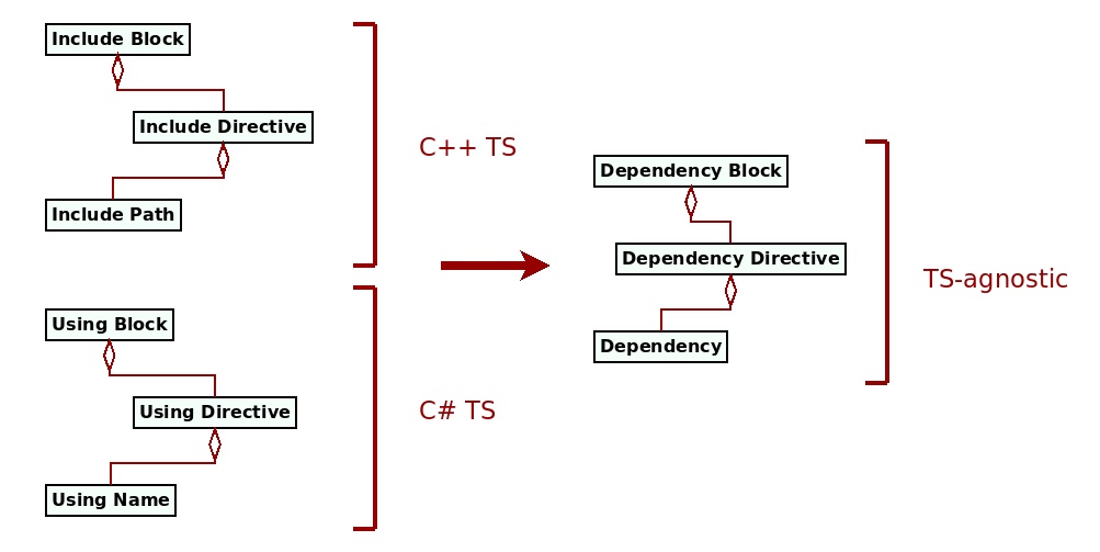
Figure 10: Dependencies generalisation.
Relations
Our last line of enquiry on file artefacts examined how they relate to each
other. In MASD, a file \(a_1\) is related to another file \(a_2\) if the
content of \(a_1\) has a functional dependency on \(a_2\), meaning that \(a_1\)
references \(a_2\).42 The reference can be an include path, the
use of a type, or any other form of textual dependency.
Mapping this example to MASD's physical domain, the file artefact
\(A_1\) — instantiated by the file \(a_1\) — has a relation with file
artefact \(A_2\) — instantiated by the file \(a_2\). In the relation, \(A_2\) is
known as the referee whereas file \(A_1\) is the referrer, as per Figure
11.

Figure 11: Relation between two files \(A_1\) and \(A_2\).
Having identified relations, the next task was to study their characteristics.
Reusing our initial project sample, three factors were uncovered which affect
relations: input variability, origin and mode of production. With regards to
input variability, the following types of file artefact relations were
observed:
- Constant relations: these cater for cases where a
file artefactis always related to other well knownfile artefacts, insensitive to both structural and non-structural variability. For example, if all C++ files implement thestd::swapalgorithm, an include of the C++ Standard Library header file<algorithm>must always be present.43 Similarly, a typical C# class will require ausing Systemstatement in order to implementToString. Both examples presume there are no switches with which to toggle these features.
- Variable relations: these are dependencies on
file artefactas a function of input variability. Given that there are two types of input variability, it is unsurprising that two types of variable relations were found:- As a function of structural variability: that is, the shape of the
bodyof a file induces a dependency on another file. For example, if type \(t_1\), defined in file \(a_1\), has an attribute of type \(t_2\), defined in file \(a_2\), it will induce a dependency on the definition of type \(t_2\), manifesting itself as arelationbetweenfile artefacts\(A_1\) and \(A_2\). - As a function of non-structural variability: meaning the configuration selected by the user creates relationships between files. For example, if a configuration enables an optional method, the method itself may necessitate the inclusion of additional types.
- As a function of structural variability: that is, the shape of the
File artefacts can also be categorised in terms of their origin, as per
Figure 12. When viewed from a MASD
perspective, file artefacts can either be exogenous — that is, created
externally — or endogenous — created and managed internally within
MASD.
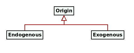
Figure 12: Taxonomy of file origins.
File artefact relations are impacted by its origin, giving rise to the
following:
- Exogenous relations: when an
File Artefactis related to one or morefile artefactswhich are not generated by MASD. This encompasses, for example, all of the files in the C++ Standard Library. Theinclusion pathfor external files is irregular — that is, it may follow any number of conventions regarding folder nesting and file naming, all of which are outside of MASD's control. If therefereeisexogenous, it must first be exposed to MASD via a PDM, containing all required information about the file via non-structural variability, including a mapping to irregular paths. - Endogenous relations: when a
file artefactis related to one or morefile artefactsgenerated by MASD, either within the same product or from a different product. Theinclusion pathof internal files is regular; that is to say, MASD is able to enforce a convention for the include path, making it largely — if not entirely — a function of structural variability (see the Folder Artefacts section).
Finally, a concept closely related to a file artefact origin is its mode of
production — that is, how it was originated. Files have three distinct modes
of production: manual, when produced by humans, automated, when produced by
machines and partially automated, when produced by a combination
of the two. Figure 13
depicts these three different modes in diagrammatic form. A file produced
manually is commonly known as handwritten or handcrafted. Since the main method
for the automated production of files is code generation, these are known as
code-generated or simply just generated. Finally, files produced in part by
automated means are known as partially generated / automated, and require the
merging of handwritten and generated content to attain the file's final form.
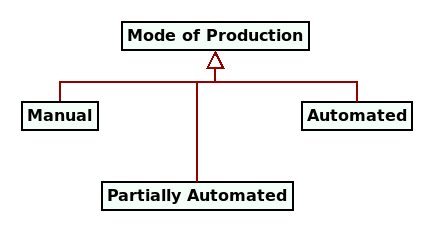
Figure 13: Taxonomy of modes of production.
A software project that contains both handwritten and generated files, partially
or fully, will require one or more integration strategies
(Greifenberg, Timo and Hölldobler, Katrin and Kolassa, Carsten and Look, Markus and Nazari, Pedram Mir Seyed and Müller, Klaus and Perez, Antonio Navarro and Plotnikov, Dimitri and Reiss, Dirk and Roth, Alexander and others, 2015) (Greifenberg, Timo and Hölldobler, Katrin and Kolassa, Carsten and Look, Markus and Nazari, Pedram Mir Seyed and Müller, Klaus and Perez, Antonio Navarro and Plotnikov, Dimitri and Reiss, Dirk and Roth, Alexander and others, 2015a). The mode of
production is significant to the MASD domain architecture because it
is responsible for setting out the menu of
available integration strategies to its end users; these strategies impact file
relations. Given that exogenous Referrers are outside of MASD's
remit by definition, one needs to focus only on endogenous referrers and
thus arrives at the following permutations:
- Fully generated referrer. MASD is made aware of this relationship
via input variability — structural or non-structural, depending on the case.
This encompasses a number of sub-cases for the
referee— e.g. endogenously generated, endogenously partially generated, endogenously handwritten, exogenous — but on all cases, its details must exposed into the system; this is done via regular MASD models for all endogenous cases and via PDMs for the exogenous case. - Partially generated referrer. The generated portion of the file is handled as per the previous case. However, the handwritten portion of the file, created via protected regions, may bring in additional relations which MASD must generate. These are made known to MASD via input variability.
- Handwritten referrer. The user is responsible for creating the file, as well as managing its relations. However, the relations must also be made known to MASD via input variability, because they may impact other files such as build files.
Joining all of these dots, one is forced to conclude that all file relations
must be exposed to MASD, regardless of origin or mode of
production, if text file reconstruction is to be achieved; and input
variability, either structural or non-structural, is how MASD is to be
made aware of those relations. This isn't by any
means a novel conclusion — it has been MDE's long held position
that everything within a software product should be modeled — but it is
nonetheless significant that bottom-up analysis (i.e. physical to logical) is
in agreement with its top-down counterpart (i.e. logical to physical).
This conclusion is also an apt end to the physical analysis of files. A similar process to what is described here was carried out for different types of text files, across multiple TSs and with bodies carrying different payloads; once we established a basic taxonomy and morphology that satisfied all our samples, our attention then turned towards characterising folders.
Folder Artefacts
Like file artefacts, folder artefacts also have an underlying structure,
albeit simpler, and therefore it too can be unearthed via the physical modeling
process. The analysis is presented in three
parts. First, we discuss the folder taxonomy revealed by dissecting our sample,
which includes terse descriptions of the identified
elements. Next, the interaction with different forms
of input variability is investigated. Finally, examples are provided to clarify
all concepts discussed.
Taxonomy
Folder artefacts possess an underlying taxonomy because folders serve
different purposes within a software product, storing distinct types of file
artefacts. Of course, products may be organised
in any number of possible folder hierarchies, each a function of complex
variables such as the prevailing coding
standards, IDEs and other build tooling, the target TS and
many more. For example, a "typical" Java folder structure
({Maven Project}, 2021) is noticeably distinct from that of C#
({Microsoft}, 2021), with both TSs having experienced a considerable
amount of change since inception. C++ is further complex still, spanning the
widest range of structural variation of all considered
TSs.44
A component is divided into one or more parts; components with a single
part may omit the part folder. Parts were originally introduced to cater
for the filesystem layout of C++ projects, which often store public header files
in a different directory from that of private headers and implementation files
— e.g., the idiomatic include and src directories.
However, the concept has been subsequently generalised to cater for other
artefact groupings such as MASD models, as well as component
documentation, both of which reside on their own top-level folder within a
component. Figure 15 illustrates the generalisation via a
part taxonomy with two TSs, and depicts a number of sample parts
for each.
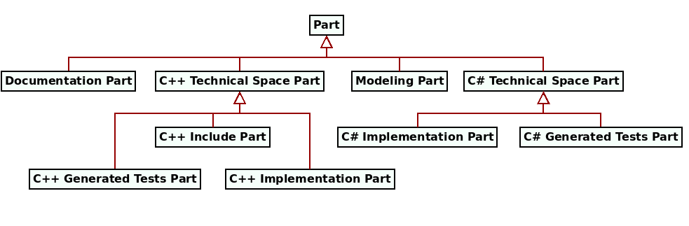
Figure 15: Simplified part taxonomy.
Parts may be further sub-divided into facets. A facet is a container for a
set of related file artefacts , all belonging to the same TS, and was
introduced as the mechanism to implement the composition of trivial structural
functions via positive variability techniques (Figure 16).
Facets align closely with the types of input variability
functions identified in Figure 5, and can
be thought of as the containers of the concrete artefacts that emerge from this
process — e.g. the C++ type definition facet contains class type
definitions, enumeration type definitions and so on.
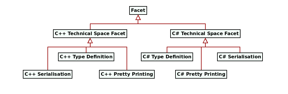
Figure 16: Sample facet taxonomy.
It is within the facet that MASD's physical domain finally meets
the major TS's domain via modules. Modules are the physical
representation of the programming language concept of package or
namespace, and their expression is mostly controlled by
structural variability, though non-structural variability also plays a vital
role as the next section will explain.
Input Variability
Folder artefacts are also functions of input variability, though, as with the
taxonomy, the observed variation is narrower than that of files. Input
variability interacts with folder artefacts in the following manner:
- Structural variability determines the object graph of the physical model
entities within MASD that are part of the
folder artefacttaxonomy. For example, theproductand its associated properties, itscomponents, availablefacetsand so on. - Non-structural variability controls, amongst other things, how the
object graph is transformed into
entities on a filesystem. For example, if a
componenttargets a single TS, non-structural variability determines whether a TSfolder artefactis expressed into a folder or not. Non-structural variability can also used to override default names of expressed folders — e.g. changing the name of the C++ TS folder fromcppto saycxx, etc.47
And with this we have now introduced the main concepts regarding folder
artefacts in MASD. Let us now turn to examples of their application,
to bring these concepts to life.
Examples
The terse definitions of the previous sections will now be made clearer by
reviewing four snapshots taken from our sample projects. These were selected so
as to portray the elements identified thus far from different viewpoints. A
UML package diagram is used to represent folder
artefacts, with composition indicating containment — thus simplifying
diagram structure — and stereotypes signifying MASD physical types.
The diagrams also introduce the use of colour, which is exploited throughout
MASD to convey the various meta-elements in a distinctive
manner.48, 49
The first example is sourced from MASD's C++ reference model
cpp_ref_impl. It contains a fragment of the
product directory structure and is depicted by Figure
17. The image shows a selection of top-level
components for the product, with facets and modules being deferred to
subsequent examples.
The Physical Metamodel
The entities described thus far in this chapter are part of MASD's PMM. The PMM defines the geometry of physical space in MASD. Physical space has an hierarchical nature, which is to be expected given its entities emanate from a hierarchical filesystem. Figure 23 exemplifies the relationship between the metametamodel (M3), the PMM (M2) and the PM (M1) by populating a metamodel hierarchy with a small number of sample entities. Files in the filesystem (M0) have been omitted for brevity.
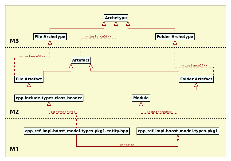
Figure 23: Example MASD metamodel hierarchy.
In the figure, MASD's metametamodel is comprised of archetypes, divided into file archetypes and folder archetypes. Within the metamodel, the archetypes are instantiated by artefacts such as file artefacts and folder artefacts. The figure then goes on to supply examples for both artefact types and, of these, the file artefact example is of special interest due to its name:
cpp.include.types.class_header
The notation denotes a fully-qualified physical meta-name and it is a physical address within MASD's physical space; it conveys a point in that space. To bring the notion home, let us look at a few more example archetypes:
cpp.include.types.enum_headeris the archetype responsible for generating the definition for a C++ enumeration. It exists within thecppTS, theincludepart and thetypesfacet.cpp.src.types.class_implementationis the archetype that generates the implementation of a C++ class. It exists within thecppTS, thesrcpart and thetypesfacet.csharp.main.types.classis the archetype responsible for generating the definition of a C# class. It exists within thecsharpTS, themainpart and thetypesfacet.
More generally, physical addresses take the following form:
[technical space].[part].[facet].[archetype]
Besides just points, physical addresses can also be used to denote regions of physical space, which are sets, in the mathematical sense, of physical entities. For example, cpp contains all parts, facets and artefacts in the C++ TS; cpp.include is a subset of cpp and contains all facets and artefacts within that part. The geometry of physical space brings structure to the modeled physical patterns but, more significantly, the space is arranged in this fashion to facilitate the management of variability of physical entities — a topic of later analysis (cf. the Variability Domain section).
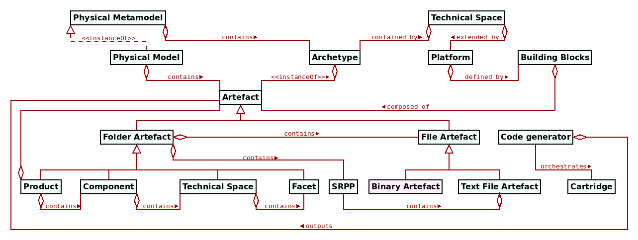
Figure 24: Fragment of the PMM.
Figure 24 provides a birds-eye view of the PMM and related entities, bringing together all of the elements discussed thus far as well as introducing two new ones — platforms and cartridges — which, due to their complexity, will be dealt with by the next section (cf. the Platforms and Cartridges section). The image is largely a collage of previous diagrams, with a few noteworthy points. First, TSs are shown twice to illustrate their dual nature in MASD: for endogenous purposes, they represent folder artefacts, but for exogenous purposes they are seen as sets of platforms. In addition, we see archetypes associated with the PMM though we previously alluded to a metametamodel; in practice, MASD opted for folding the metametamodel into the metamodel — that is, for employing loose metamodeling rather than strict metamodeling (Marco Craveiro, 2021) (Section 3.4). It was done so because the PMM was designed to cater for specific two use cases:
- To generate the code generator; that is, elements such as TSs,
parts,facetsandartefactswere modeled as SRPPs themselves. This was done by applying the physical modeling process to the development of the code generator, and extracting physical patterns, which were modeled and catalogued just as any other physical pattern. - To serve as the target of refinement; that is, logical entities are transformed into physical entities via transform chains, and these physical entities are subsequently transformed into files and directories in the filesystem.
Loose metamodeling was sufficient to satisfy both of these use cases, so it was preferred to strict metamodeling. This "use case focused" approach is also in keeping with the vision for the methodology — targetting narrow application and thus affording simpler solutions when compared to more ambitious applications of MDE. Loose metamodeling is not without its costs, however, and terms such as archetypes and artefacts are where its limitations start to show. These two terms are used through MASD, and at times it may appear that they are interchangeable; however, as the metamodel hierarchy already alluded to, they serve different roles in MASD's domain architecture. The choice of term is meant to denote the level of abstraction at which one is operating:
- the term
archetypeis used in the following contexts: 1) when we are referring to the generating function that creates instances of individual artefacts; 2) when we want to describe sets of artefacts, such as regions of physical space. - the term
artefactis employed when we want to classify a set of files, or when we have an artefact instance in memory for example.
And with this clarification, we are close to completing our survey of the physical domain. Before we do so, there are two additional physical entities we need to cover, and these are of a different nature of those identified thus far.
Platforms and Cartridges
The artefact-centric view of the world posited by the physical domain is instrumental in addressing some of MDE's ambiguities in its vocabulary, previously described in the state of the art chapter and (Marco Craveiro, 2021) (Chapter 4). This section explains how it is used to characterise two important concepts, pertaining to two key entities within MASD's physical domain: platforms and cartridges. We start with the former.
A platform is understood to be an aggregation of building blocks within a TS (cf. Figure 24) — that is, a named and possibly versioned set of artefacts which, for all intents and purposes, is indistinguishable from a software product. The only difference between the two is that MASD deems products to be artefact collections it generates — i.e., endogenous — whereas platforms are external to it and can only be accessed by means of an associated PDM (cf. the Logical Domain section) — i.e, exogenous. In other words, platforms lack the regularity afforded to MASD software products — thus requiring mapping — and are responsible for raising the abstraction level — thus simplifying the generating functions. Figure 25 illustrates MASD's artefact-centric and hierarchical view of platforms.
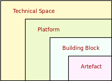
Figure 25: Technical Space composition
Whilst broad, this is nonetheless a definition that contains no ambiguity; a TS defines the syntax via its metamodel, and platforms are sets of artefacts that are valid instantiations of the syntax, and which have not been created by MASD. With this we avoid questions such as "is the CLR a platform?" or "is the JVM a platform?" (Marco Craveiro, 2021) (Chapter 5), as these are not meaningful in a MASD context. If there is a library exposing the internals of the CLR or the JVM, then these libraries are considered platforms. More broadly, MASD is only interested in statements involving sets of physical artefacts.
Cartridges are of a similar nature to platforms with regards to their endogeneity.53 They are defined as any code generator external to MASD whose input can be modeled as a text artefact generated by MASD, and whose output is a set of text artefacts on which MASD may perform further processing. The cartridge entity in the PMM (cf. Figure 24) models aspects of the external code generator such as its version and any other properties that have a functional dependency on the input artefacts generated by MASD.54 In this way, the role of the cartridge entity is similar to that of the PDM: it regularizes external entities for consumption by MASD. From this perspective, MASD works as an orchestration framework for cartridges, requiring only minimal knowledge about the cartridges themselves; significantly, this is merely a by-product of the fact that cartridge inputs are sources of SRPPs.
MASD's interplay with cartridges is perhaps best understood by example. Let us consider MASD's integration of the tools ODB55 and clang-format56, two tools popular with C++ developers. MASD consumes these tools via a workflow with the following steps:
- Step 1: MASD generates the input files for ODB whenever users request RDBMS support for a given C++ project.
- Step 2: MASD supplies the input files to ODB, which generates a set of C++ files implementing the database layer.
- Step 3: MASD supplies the output of ODB to
clang-format, which indents the source code according to a user-defined convention.
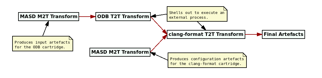
Figure 26: Example cartridge pipeline.
This workflow is implemented in the MRI as a cartridge pipeline, as depicted graphically in Figure 26. Regular M2T transforms are used to implement Step 1, whereas Steps 2 and 3 are exposed to the MASD framework as Text-to-Text (T2T) transforms — i.e., receiving artefacts as inputs and producing artefacts. Note that the T2T transforms are composed into a transformation pipeline to produce the desired output, as they are parametrised by non-structural variability — i.e., users can decide if they would like RDBMS support and/or source code formatting. In addition, the T2T transform encapsulating clang-format has an input artefact with configuration specific to the tool; it is generated by a M2T transform within MASD.57
Platforms and cartridges enable MASD to access the outside world. However, their modeling is seen as an instance of a more general process: ultimately, MASD extracts a general set of modeling entities from within the physical domain. These entities live in MASD's logical domain, and it is to it we shall turn to next.
Logical Domain
The logical domain is the portion of MASD's problem domain that deals with logical elements extracted from supported TSs, alongside with their relationships and variability requirements.58 Unlike its physical counterpart, the logical domain is large in terms of footprint as it models an ever growing number of entities, and manifests a trend that is expected to continue over time. Nevertheless, from the perspective of the domain architecture, its role can be condensed to just two key themes: an overall characterisation of its composition (the Composition section) and an analysis of the projections in and out of logical space (the Projections section). The next two sections cover these two themes respectively.
Composition
MASD's Logical Metamodel (LMM) is an instance of the Logical Metamodel (LMM), responsible for housing meta-elements modeling entities of interest within the logical domain. The LMM also caters for the various types of logical models such as PIMs, PSMs and PDMs — which, as already mentioned, are the gateway for exposing platforms to MASD. The LMM was created with Piefel and Neumann's ideas in mind (Piefel, Michael and Neumann, Toby, 2006), in that it is an intermediate model designed specifically for code generation and serves no other purpose.59 The majority of the entities housed in the LMM originate from generalisations of elements uncovered via physical analysis and design (the Physical Domain section), via the process depicted by Figure 27.
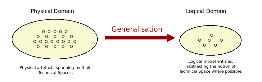
Figure 27: Logical generalisation of physical concepts.
Nonetheless, it is important to note that the TS metamodel is also of great relevance to the shape of the logical entities; there is a natural relationship between constructs in the TS's metamodel and the patterns we are trying to capture in the LMM, as demonstrated by Figure 28. The bottom part of the diagram, in yellow, points out useful sources for logical entities given common elements in TSs; it is a logical view of the argument already put forward from a physical perspective via trivial structural functions (the Physical Domain section).60
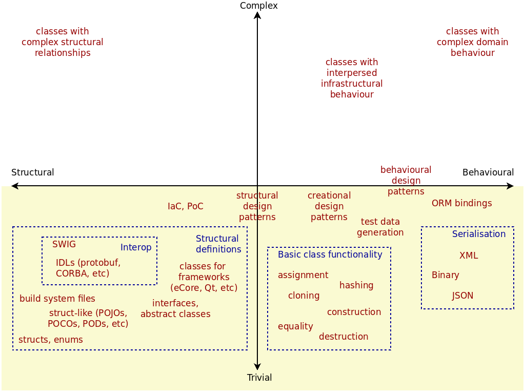
Figure 28: Characterisation of TS entities.
The free-style depiction used in the figure also tries to elicit the dangers of reading too much into the relationship between the TS's metamodel and MASD's logical representation. A construct is only relevant to MASD's logical model if it captures all the information required to create a projection of said construct into the physical domain (the Projections section). The TS metamodel offers a good source of inspiration for the identification of these logical elements; however, the objective of the LMM is not to replicate a TS's metamodel but instead to abstract commonalities between them, from the perspective of the projections. In this vein, as depicted in Figure 28, it is often necessary to break down TS metamodel entities, such as classes, into constituent parts — assignment, cloning, construction and so on — or finding higher level constructs which are not directly relevant to the TS metamodel — such as design patterns. Therefore, by observing patterns of use within text artefacts, we model at varying levels of abstraction when compared to the TS metamodel, as well as modeling languages such as UML — both of which designed for different use cases. This is perhaps best understood by looking at modeled entities and their groupings. Figure 29 provides a high-level overview.
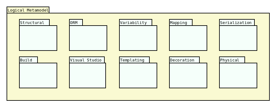
Figure 29: Packages within the LMM.
At present, the LMM is made up of ten distinct packages, each targetting a distinct area of a software product.61 Their intent can be summarised as follows:
- Structural: Models structural variability within programming languages. It is the portion of the LMM that is the closest to programming language constructs.
- Build: contains entities responsible for build files such as Makefiles and CMake files, often used on UNIX-like operative systems.
- ORM: provides support for RDBMS, including tools such as ODB.
- Visual Studio: models the infrastructure needed to support the Visual Studio IDE, used on Windows platforms.
- Variability: contains all entities required to generate non-structural variability support in the MRI (the Variability Domain section).62
- Templating: models entities related to logic-less templates, used in MASD to create M2T transforms.
- Mapping: support for PIMs is attained via these entities, which provide the infrastructure to map TS-agnostic types to their TS-specific counterparts.
- Decoration: contains all entities modeling file artefact decoration, as uncovered by morphological analysis (the Artefacts section).
- Serialization: provides support for entities required in a serialisation context.
- Physical: Models MASD's physical entities such as parts, archetypes, relations and the like; contains the LMM's representation of the PMM, and it is used to generate it.
As there are over one hundred individual classes in the LMM, it is not
feasible — nor necessary — to cover each of them in detail. It is however
worthwhile sampling one of the packages in order to get a flavour for how these
elements are modeled. Figure 30 does just so, providing
a glimpse of the main components in the LMM's structural package.
Most of the depicted elements are
TS-agnostic representations of metatypes commonly found in
programming languages, but there are a few noteworthy exceptions which warrant a
fuller description — as do the varying levels of abstraction, denoted in the
figure by the colour scheme.63
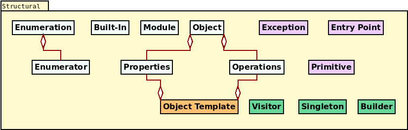
Figure 30: Classes in the structural namespace.
Module, enumeration and built-in model, respectively, namespaces (or
packages), enumerations and built-in types. Object is intended to stand for
DTOs, though at present is synonymous with the TS concept of
class, containing both properties
(attributes) and operations.64 Grouped together, these four
elements and their dependent types (in light blue) can be thought of
generalisations of the "traditional metatypes" found in a programming language
TS, as well as modeling languages such as UML.
Moving upwards in the abstraction ladder, we then have a second group of metatypes, in purple, which exist at a higher level of abstraction from that of the TS metamodel, and which we named idiomatic metatypes. These are as follows:
- Exception represents types that denote error conditions. During the
projection into physical space, MASD takes care of all of the
machinery needed to make them idiomatic in
the target TS, such as inheriting from
std::exceptionin C++ orSystem.Exceptionin C#. They can also be mapped to error codes where the TS has support for these — e.g. the C language. - Primitive is a wrapper around a built-in type that allows the creation of
strong primitive types. For example, instead of using
std::stringto denote a unique identifier for a person, MASD allows the creation of a specialised primitive type for this purpose — e.g., aPersonId, with an underlying type ofstring.65 - Entry point represents the function where program execution begins —
e.g.,
mainin the C/C++ TS and, typically, its C# counterpart ofMain.
All of these entities should be familiar to software developers, with more of their ilk to be added in the near future such as named key-value pairs, units (e.g. support for units of measure like the metric system), named bitsets and the like. Types in this grouping are mainly related to idioms, uses and conventions that often span multiple TSs, but are restricted to a single type.
Moving up the abstraction ladder once more takes us to the GoF's
design patterns (Vlissides, John and Helm, Richard and Johnson, Ralph and Gamma, Erich, 1995); these are shown in green on the
diagram. Design patterns distinguish themselves from idiomatic use cases by
being larger aggregates, usually involving the collaboration of multiple
classes. The MRI only supports the
visitor pattern (p. 331) at present — applicable whenever inheritance is
employed — but other patterns such as singleton (p. 127) as well as
builder (p. 87) are currently under development. Though they are being accrued
incrementally, it is expected that the majority of the GoF patterns
will eventually be represented within the LMM.66
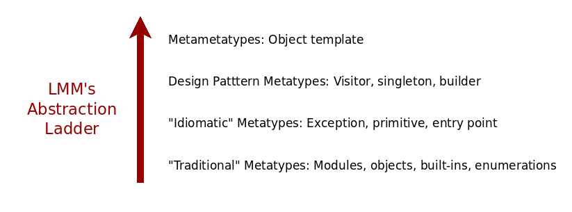
Figure 31: Abstraction ladder in the Structural package.
From design patterns, the level of abstraction is raised one final time; Figure
31 captures the entire ascent over the
abstraction ladder. Object templates are to be found at this highest level
(Figure 30, in orange). They allow the creation of
modeling entities that exist only at modeling-time,
and demonstrate the power of employing loose metamodeling in this context.
Object templates were inspired on C++ concepts67, because they
abstract classes with the same shape, though entirely unrelated from the
TS's type system perspective. In addition, now that C++ 20 has
introduced language-level concept specifications, MASD is looking into
projecting object templates into the physical domain via the new language
feature. Regardless of this new use case, object templates have already proven
extremely useful to the MRI, and are used extensively throughout
MASD's code generator. Their use may not be entirely obvious,
however, so a small example is required to clarify how it and other LMM
metatypes are employed in practice.
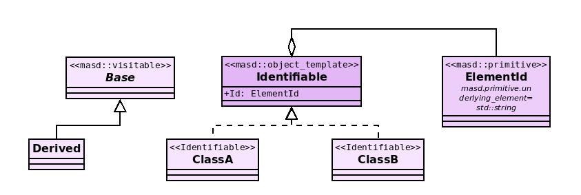
Figure 32: Example model with a selection of LMM metatypes.
Figure 32 does so by portraying a UML class
diagram that instantiates object templates, objects, primitives and
visitor. MASD metatypes are supplied as UML stereotypes,
contained within the MASD UML profile. First, we turn out
attention to object templates. The
metatype Identifiable dynamically generates a new stereotype, in this case
applied to types ClassA and ClassB; both classes will be generated with a
property called Id, but there will be no reference to the object template
Identifiable within the generated C++ code.68
With regards to the primitive ElementId, its underlying type is defined via
UML's tagged values, located just below the class name:
masd.primitive.underlying_element=std::string
The tag in the tagged value — masd.primitive.underlying_element —
represents an entity within MASD's variability domain (the Variability Domain section). The value of the tag represents the type std::string,
sourced from the C++ Standard Library. It is made
accessible to MASD via the PDM cpp.std, containing all
exposed types within the C++ Standard Library.
Next, we turn to visitor support, which, at present, is not without its flaws.
The element Base is annotated with the stereotype of masd:visitable,
triggering the generation of a visitor for this base type, dispatching to all of
its derived types (Derived, in this case). Alas, the approach is now
understood to be a misuse of the
LMM's type system because the visitor class itself is not present in
the class diagram, being instead generated internally.69 And
on the theme of implicit associations, the object metatype is also used
implicitly in Figure 32: UML classes without a
MASD stereotype denoting a LMM metatype default to
masd::object; thus Base, Derived, ClassA and ClassB are all implicitly
tagged as masd::object.
The analysis of the model put forward in Figure 32
concludes with a demonstration of how object templates can be linked back to
TS-specific features such as concepts. In the listing below, a sample
print function was handcrafted, with a template parameter whose name matches
the object template; the generic function can
be instantiated by any type meeting the requirements of the Identifiable
concept — e.g. ClassA or ClassB. In other words, the C++ concept maps to
our logical representation of the Identifiable object template. Note that
the listing presupposes the presence of all necessary includes for
pretty-printing of the ElementId primitive. The listing also demonstrates the
initialisation of primitive types — e.g. idA and idB.
template<typename Identifiable>
void print(const Identifiable& ident) {
    std::cout << "Id:" << ident.Id() << std::endl;
}

void caller() {
    ElementId idA("A");
    ClassA a(idA);
    print(a);

    ElementId idB("B");
    ClassB b(idB);
    print(b);
}
This example of a logical entity projected into the physical domain brings us into the general topic of projections, which the next section will develop.
Projections
As shown previously, MASD's physical domain
can be thought of as a physical space, with an associated notation for points.
The logical space is a similar construct, with its own point notation derived
from element containment. As a result, much like
physical space, logical space is also hierarchical in nature. Since modules
are the only LMM element that can contain other
elements70, the following notation describes any point in logical
space (with the word modules omitted due to space constraints):
[product].[component].[internal].[element name]
Product stands for product modules and represents the set of one or more
modules associated with the product name — e.g. Some.Product, using dot
notation, is made up of product modules Some and Product. Component
stands for component modules and represents one or more modules associated
with the component (e.g. Some.Component); and
internal — i.e., internal modules — represents zero or more modules
used internally within the component (e.g
ModuleA.ModuleB).71 Finally and predictably, element name
represents the name of the logical element, e.g. ElementA. There are clear
similarities between this approach and what was put forward in the physical
domain; Figure 33 joins them together into a single
viewpoint.72, 73
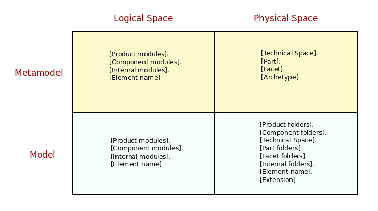
Figure 33: Notation for points in physical and logical space.
The first interesting point in this comparison is that all points in logical space use the same notation, whether when representing elements in the metamodel (e.g. the LMM) or any instance model (e.g. any LM). Since there is nothing distinctive about the LMM — it is just a regular model after all — and since we prefer loose metamodeling, there is no requirement to make a distinction between its types and any user types. On the right hand side of the diagram, at the top, we have the previously described notation for points in physical space at the metamodel level (the Physical Domain section). Finally, at the bottom right, physical paths are shown — i.e. physical points at the model level. These represent the projection of logical elements across to physical space and are a function of:
- The geometry of physical space, as dictated by the PMM, which
enforces regularity — e.g. specifies the placement of
productfolders,componentfolders,partfolders,facetfolders, etc.; - Structural variability in the logical model, which instantiates each of these elements: the product and component names are supplied by the user, as are all internal folders and the element name;
- Non-structural variability, dictating the exact configuration to select; for example, what extension to use for C++ headers, whether to express product and component folders, whether to override the name of the technical space folder, and so forth.
Paths are just one of many projections within MASD. Almost all logical
entities are projected into the physical dimension — the most obvious
exception being object templates, which at present are consumed by the
transform chains during processing and do not have a physical
representation.74 Typically, projections are functions of
structural variability, parametrised by
non-structural variability, and often implemented as M2T transforms. To
simplify matters, we shall ignore non-structural variability for the purposes of
the present discussion, as it is covered in the Variability Domain section;
but it is important to bear in mind that any such
projection will offer a number of configurable parameters which will have a
significant effect on the result of the projection.
Projections are best understood with examples. Figure
34 shows an example projection of the logical
element masd::object (the Composition section).
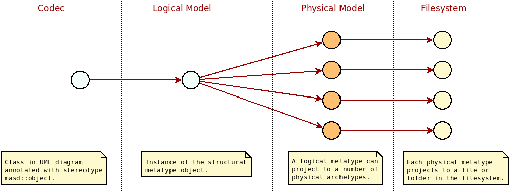
Figure 34: Projection across MASD spaces.
In the diagram, an initial representation is used as input to the process; this is known as the codec representation and it is designed to be as simple as possible.75 The idea is to make the creation of extractors a straightforward matter, allowing the implementation of a codec for each required tool, in keeping with the methodology's tenets (P-2, Integrate Pervasively, in particular). In addition, we want to keep the number of bespoke transforms in each codec to a bare minimum, leaving all the heavy lifting to common transforms. Figure 35 contains a fragment of the codec model, with the key entities.
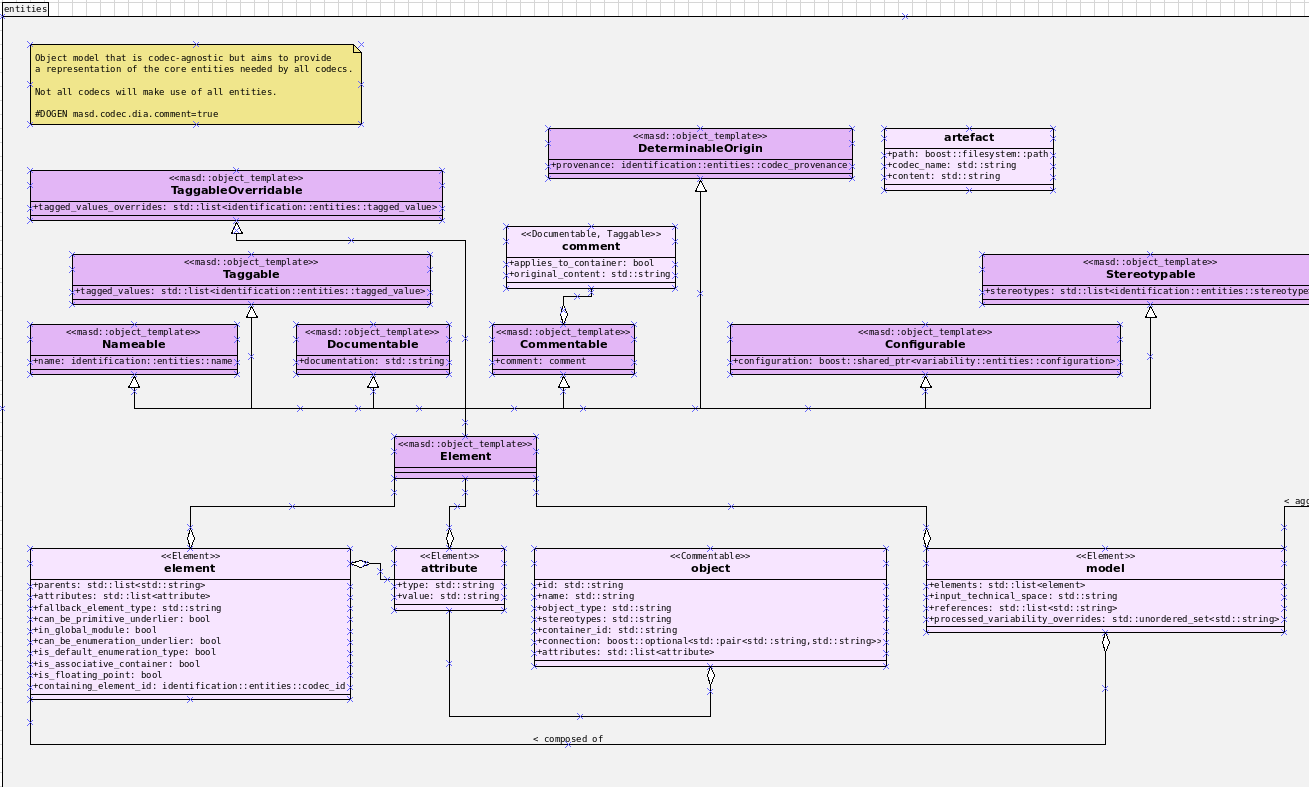
Figure 35: Key entities in the codec model.
The codec representation defines the projection of its elements into the logical
model proper, taking these ideas into account; it is always a one-to-one
projection, but because LMM elements are highly specialised, many such
projections have been defined. By and large, UML stereotypes determine
the routing to a logical element — e.g., an
element with stereotype of masd::obejct will be converted into the
LMM's structural metatype of object, an element with a stereotype
of masd::enumeration will be mapped to a structural metatype of enumeration
and so on. Elements without stereotypes are assigned a default mapping; for
example, UML classes without stereotypes default to masd::obejct.
Next we have the projections from the LMM into the PMM. These
projections are functions that take points in logical space and map them into
sets of points in physical space, often spanning multiple regions. Returning to
our example, the UML class at the codec level is first projected into a
masd::object, and then projected into the physical locations depicted by
Figure 36. The figure uses the same colouring
scheme as before, with TS, parts and facets containing archetypes. Its
not necessary to go into the details on each archetype shown — hopefully most
have self-explanatory names — but it is significant that there are a large
number of them (18, in yellow) and their number is expected to grow considerably
over time, as more patterns are added to MASD.
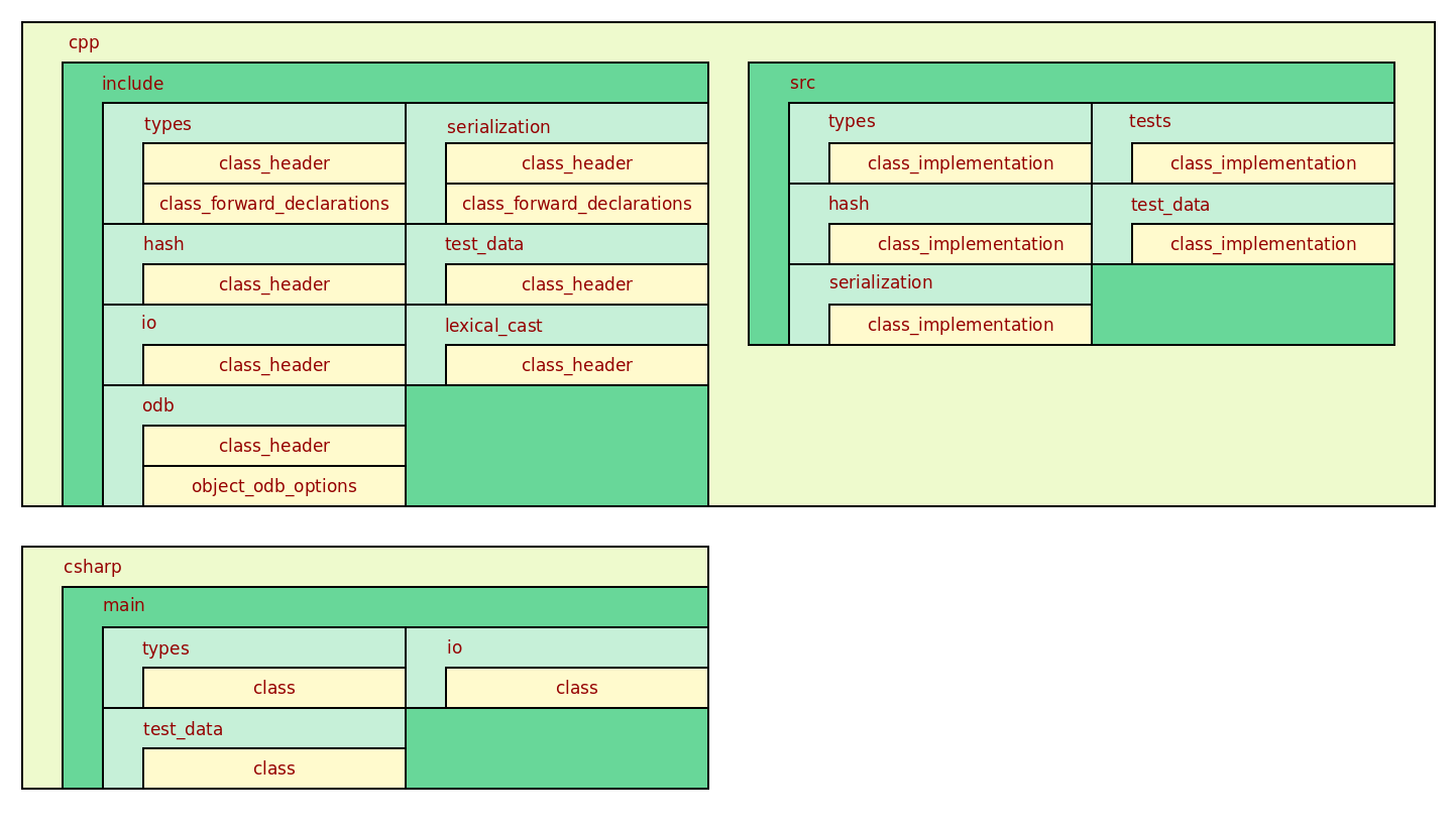
Figure 36: Projection of masd::object into physical space.
Clearly, not all functionality is required for all use cases; for example, one may require type definitions only, or type definitions with serialisation support, meaning that all other projections would not be necessary. And it is here that we enter the last domain within MASD, dealing with the configurability of logical and physical model elements, as well as the configurability of the projections between spaces.
Variability Domain
The third and last domain of interest to MASD is the variability domain; it is only concerned with the modeling of non-structural variability. As this choice may be surprising, we begin by justifying the approach (the Approach section below), and then move on to discuss the metamodel entities in the VMM (the Variability Metamodel section). Finally, the Variability Model section discusses the VM, which is concerned with how instances of the VMM are used to enable support for SPLE in MASD.
Approach
Variability is a vast and complex topic within MDE, so, to avoid confusion, all mentions in this document have been carefully qualified — up to the present section.76, 77 Unfortunately, given its prominence within MASD, it is impractical to enunciate so clearly each use of variability within the domain architecture, as doing so would make naming entities unwieldy. Furthermore, a natural alignment was observed between certain variability kinds and MASD's domains, meaning that, in practice, confusion seldom arises.78 For all of these reasons, the variability domain specialises only on non-structural variability; and the term "variability", when used in a MASD-only context, is understood to be synonymous with this kind of variability, with other uses explicitly qualified.
Once boundaries had been established, the question of how to integrate domain modeling with variability modeling emerged. Clauß (Clau{\ss}, Matthias, 2001) and Thibaut et al.'s (Possomp{\`e}s, Thibaut and Dony, Christophe and Huchard, Marianne and Rey, Herv{\'e} and Tibermacine, Chouki and Vasques, Xavier, 2010)(Possomp{\`e}s, Thibaut and Dony, Christophe and Huchard, Marianne and Tibermacine, Chouki, 2011) take on the matter was preferred over others, mainly due to their emphasis on a single integrated modeling approach that encompasses variability requirements. The simplicity of the implementation was of particular interest, since having a single model meant augmenting MASD's UML profile with a limited number of variability concepts. Whilst not as expressive as Feature Modeling or Orthogonal Variability Modeling (OVM), the approach is sufficient for the well-defined needs of MASD — especially because it lowers the cognitive load of end-users by reducing the number of concepts needed to model effectively. Having settled on the boundaries and the approach to variability modeling, our efforts then shifted towards identifying the entities of interest within this domain, covered in the next section.
The Variability Metamodel
The Variability Metamodel (VMM) is designed to provide variability services to MASD's logical and physical domains. Due to this, it's deeply intertwined with both domains, and it is used in many complex workflows. However, at its core it was created to address two simple needs:
- enabling and disabling regions of physical space, such as TS, facets and artefacts;
- configuring various aspects of the projections to physical space: naming the directories for facets, configuring file names and extensions, enabling or disabling certain features in code generation, etc.
Since in MASD variability is built atop of UML class diagrams,
we made use of tagged values to convey configuration.79 As an
example, a masd:object can be configured to enable two regions of physical
space — types and hash — by supplying the following tagged values:
masd.cpp.include.types.enabled=true
masd.cpp.src.types.enabled=true
masd.cpp.include.hash.enabled=true
masd.cpp.src.hash.enabled=true
Boolean values are one of many possible types for tagged values. Over time, MASD accrued many additional types and a type system was created in order to validate user input, as well as to facilitate the processing of these entities within the MRI. Figure 37 shows the available value types at present, with more on the pipeline.
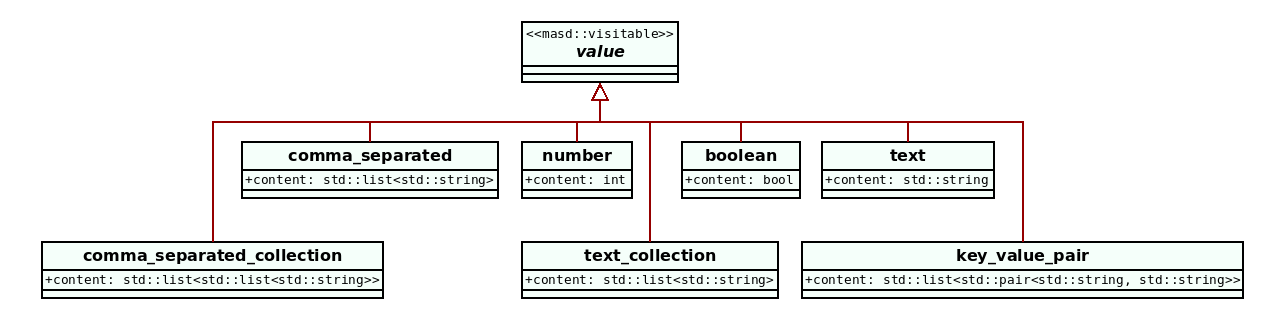
Figure 37: Value and its descendant types.
As with values, a similar problem was faced with regards to tag validation.
Initially, ad-hoc code was written for
each new tag as they were introduced but, once enough use cases were collected,
the notion was generalised via the introduction of features and
configurations. Features implement a simplified version of the concept as
found in Feature Modeling, allowing the creation new configuration points
within the domain architecture. Features are grouped into semantically related
sets called feature bundles. Figure 38 shows a small
subset of the feature bundles defined in the LMM. There we can see
that the LMM metatype feature_bundle is instantiated, with each
instantiation containing a number of features of varying types.
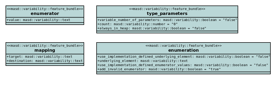
Figure 38: Fragment of feature bundles defined within the LMM.
Note that feature bundles themselves also make use of the variability
machinery. For example, features have binding points — that is,
each feature must enunciate the set of
meta-entities that can legally make use of it — and these are declared via
variability, as are other configurable elements:80
masd.variability.default_binding_point=element
masd.variability.key_prefix=masd.type_parameters
Features are useful in isolation, but MASD's approach of having a
dynamically expanding PMM posed a challenge: as new TSs,
parts, facets and archetypes were added, there was a need to model individually
their respective features, such as for example enabled as per previous
listing. The process was error prone and
repetitive, so the notion of feature templates was introduced. These are
abstract features which must be instantiated over a domain in order to become
concrete features — i.e., made available to end-user diagrams. Figure
39 shows how features such as enabled are defined as
templates.
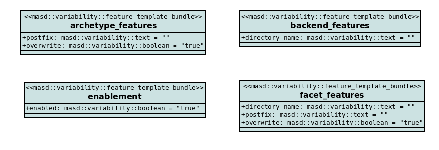
Figure 39: Fragment of feature templates defined within the PMM.
Each of these modeling elements declares a domain over which template
instantiation is to be performed. For example, archetype_features has the
following tagged value:
masd.variability.instantiation_domain=masd.archetype
The domain masd.archetype covers all available archetypes across the entirety
of the PMM. Other domains exist such as masd — spanning the whole
physical space — masd.facet, including only facets — and so forth. This
scheme allows the fine-grained definition of features across the different
regions of the PMM. At present, the main
source of domains has been the geometry of physical space, but there is no
direct connection between the domain as a variability concept and the
PMM; these are merely seen as sets of strings, meaning other
applications are possible. At present, no additional use cases have emerged.
Significantly, the VMM resulted from the application of the physical
modeling process (see the Physical Modeling section) to the MRI itself.
All of the generalisations presented here emerged from a long iterative process,
with several years of experimentation — from detecting SRPP's
within the variability domain, through to modeling them in the LMM and
ultimately to generating code to encapsulate them
as trivial structural functions — and this process is still ongoing. For
example, one area where support is limited at present is in declaring
relationships between features; once implemented, it will allow solving for
valid configurations.81 And configurations brings us to the final
topic within variability: the Variability Model (VM).
The Variability Model
All entities described in the VMM thus far are mainly used for the code
generation of variability support in the MRI. However, a second aspect
of variability is the creation of run-time configurations, which instantiate
the available features with specific values. The simplest case of a
configuration was already covered, which is to add all configuration points
to the affected elements via tagged values. However,
a problem soon emerged with regards to reusing configurations: once features
were made available and used throughout, it became obvious that component models
for a given product shared a great degree of commonality configuration-wise, as
did products from the same product line.
This use case was addressed by introducing profiles to the
LMM82. These are bundles of configuration points
that can be bound to logical elements such as component models and objects. With
the introduction of profiles, the VM took a renewed relevance,
meaning each product can now define a configuration model
describing a configuration language for the product or product line, and it
can then be reused across a set of component models. Figure
40 shows a fragment of the MRI's configuration,
with a number of profiles (stereotype masd::variability::profile). The use
of inheritance enables the construction of elaborate trees of profiles,
supporting simultaneously minimal duplication and fine grained configuration.
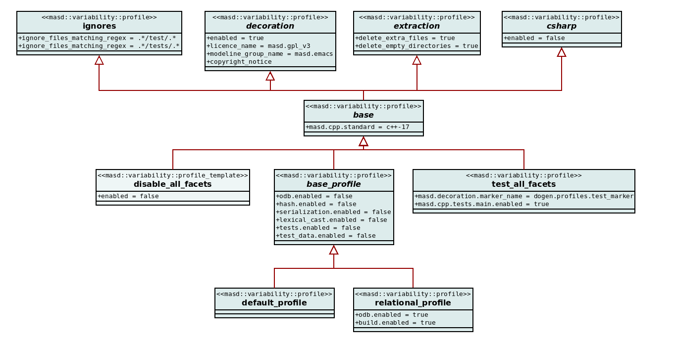
Figure 40: Fragment of the MRI configuration.
A second point of interest in the figure is the use of profile templates.
These follow the same logic as do feature templates, allowing for the
instantiation of a configuration point over a domain. Its main use, as per the
image, is in enabling or disabling all regions of
physical space of a given type (facets, in the example). Much like feature
templates, they are very useful given the ever expanding geometry of
PMM, saving users from duplicating configuration points.
As already alluded to, another extremely important aspect of profiles is how,
via their names, they can be used to create a very useful
DSL that describes the intended characteristics of various model
elements. Figure 41 shows a number of profiles
used in the MRI, all named after the abilities they convey, such
as for example serializable or hashable. To further
increase the relevance of this DSL, one can associate a colouring
scheme with profiles, making the diagrams
visually distinctive.
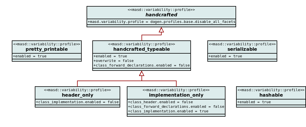
Figure 41: Sample MRI profiles.
Once defined, profiles can then be bound to models and model elements in one
of two ways: either via variability or via stereotypes. The latter takes the
same approach as object templates — i.e. one can
populate element stereotypes with one or more profiles names, thus binding the
profile with the element.83 The former is achieved by
applying the profile tag to the element in question:
masd.variability.profile=default_profile
To facilitate the detection of binding errors — such as binding a
profile that was meant for a model against an element such as object —
MASD allows setting the scope of the
binding on a profile; e.g., the following configuration point ensures
that a profile can only be bound to a model:
masd.variability.binding_point=global
Whilst workable, this high-level specification of scopes does not address all of
the present use cases. As with feature binding, more work is needed in order
to satisfy the fine-grained binding specifications we need for the current
uses across logical and physical domains. And with this, we have now introduced
all of the core domains that make up MASD's domain architecture. What
remains is to join the dots between these three domains, forming a combined
space.
The Logical-Physical Space
The domain architecture as described thus far suggests three unconnected domains with their associated models and metamodels, which may be composed to address the methodology's requirements. MASD has indeed started in this disjointed manner but, as the problem domain understanding deepened, they were fused together conceptually and the amalgam became the Logical-Physical Space (LPS). The key idea behind the LPS is that the PMM, LMM and the VMM are distinct dimensions of a multidimensional space, but they only make sense when viewed as a whole. The LPS is designed to allow elements to move seamlessly from representation to representation, all the while catering for configurability — as shown in Figure 42.
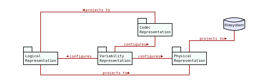
Figure 42: High-level view of MASD LPS.
From this standpoint, MASD's role is two-fold: a) to define the composition of all dimensions in the LPS — that is, the metamodels with their elements and associations; and, b) to define a framework of projections between LPS dimensions. The MRI is the canonical implementation of both of these points. The framework is responsible for taking models from a codec representation, processing them through a series of transform chains that aggregate transforms of various kinds (e.g. M2M, M2T, T2T), most of which parametrised by non-structural variability, to their ultimate destination which are files and directories in the filesystem. More succinctly: the LPS is MASD's domain architecture.
And so concludes our incursion into MASD's domain architecture, which also marks the end of our exposition of the methodology and components. The next part of this work will concern itself with its practical application, starting with its approach to the modeling activity itself.
Bibliography
Abrahams, David and Gurtovoy, Aleksey (2004). C++ template metaprogramming: concepts, tools, and techniques from Boost and beyond, Pearson Education.
Batory, Don (2005). Feature models, grammars, and propositional formulas.
Clau{\ss}, Matthias (2001). Generic modeling using UML extensions for variability.
Coad, Peter and Luca, Jeff de and Lefebvre, Eric (1999). Java modeling color with UML: Enterprise components and process with Cdrom, Prentice Hall PTR.
Czarnecki, Krzysztof and Wasowski, Andrzej (2007). Feature diagrams and logics: There and back again.
Del Gaudio, Rosa and Branco, Ant{\'o}nio (2009). Language independent system for definition extraction: First results using learning algorithms.
Evans, Eric (2004). Domain-driven design : tackling complexity in the heart of software, Addison-Wesley.
Greifenberg, Timo and Hölldobler, Katrin and Kolassa, Carsten and Look, Markus and Nazari, Pedram Mir Seyed and Müller, Klaus and Perez, Antonio Navarro and Plotnikov, Dimitri and Reiss, Dirk and Roth, Alexander and others (2015). A comparison of mechanisms for integrating handwritten and generated code for object-oriented programming languages.
Greifenberg, Timo and Hölldobler, Katrin and Kolassa, Carsten and Look, Markus and Nazari, Pedram Mir Seyed and Müller, Klaus and Perez, Antonio Navarro and Plotnikov, Dimitri and Reiss, Dirk and Roth, Alexander and others (2015a). Integration of handwritten and generated object-oriented code.
Groher, Iris and Voelter, Markus (2007). Expressing feature-based variability in structural models.
Groher, Iris and Voelter, Markus (2009). Aspect-oriented model-driven software product line engineering, Springer.
Hebenstreit, Gernot (2007). Defining patterns in translation studies: Revisiting two classics of German Translationswissenschaft, John Benjamins Publishing Company.
Hutchinson, John and Rouncefield, Mark and Whittle, Jon (2011). Model-driven engineering practices in industry.
IEEE (2018). IEEE Standard for Information Technology–Portable Operating System Interface (POSIX) Base Specifications, Issue 7, IEEE Std 1003.1-2017 (Revision of IEEE Std 1003.1-2008).
Kottemann, Jeffrey E and Konsynski, Benn R (1984). Dynamic Metasystems for Information Systems Development..
Marco Craveiro (2021). Notes on Model Driven Engineering, Zenodo.
Marco Craveiro (2021a). Survey of Special Purpose Code Generators, Zenodo.
Mellor, Stephen J (2004). Agile mda, MDA Journal, www. bptrends. com June.
Piefel, Michael and Neumann, Toby (2006). A Code Generation Metamodel for ULF-Ware, Humboldt-Universit{\"a}t zu Berlin, Mathematisch-Naturwissenschaftliche Fakult{\"a}t II.
Possomp{\`e}s, Thibaut and Dony, Christophe and Huchard, Marianne and Rey, Herv{\'e} and Tibermacine, Chouki and Vasques, Xavier (2010). A UML Profile for Feature Diagrams: Initiating a Model Driven Engineering Approach for Software Product Lines.
Possomp{\`e}s, Thibaut and Dony, Christophe and Huchard, Marianne and Tibermacine, Chouki (2011). Design of a UML profile for feature diagrams and its tooling implementation.
Tufte, Edward R and Goeler, Nora Hillman and Benson, Richard (1990). Envisioning information, Graphics press Cheshire, CT.
Vlissides, John and Helm, Richard and Johnson, Ralph and Gamma, Erich (1995). Design patterns: Elements of reusable object-oriented software, Reading: Addison-Wesley.
Waskom, Michael L (2021). Seaborn: statistical data visualization, Journal of Open Source Software.
{Boilerplate text} (2021). Boilerplate text — {W}ikipedia{,} The Free Encyclopedia.
{Boris Kolpackov} (2021). The build2 Toolchain Introduction.
{Colby Pike} (2018). Project Layout - Survey Results and Updates.
{Colby Pike} (2021). The Pitchfork Layout (PFL).
{ISO} (2020). {ISO/IEC 14882:2020(E) Information technology — Programming languages — C++}, {ISO}.
{ISO} (2011). C11 Standard.
{Kevlin Henney} (2021). Exceptional Naming.
{Maven Project} (2021). Introduction to the Standard Directory Layout.
{Microsoft} (2021). Organize your project to support both .NET Framework and .NET.
{Nim Project} (2022). Nim Programming Language Homepage.
{Nim Project} (2022a). Nim Manual.
{Single-responsibility principle} (2021). Single-responsibility principle — {W}ikipedia{,} The Free Encyclopedia.
Footnotes:
MASD's domain architecture and all of its related topics developed in this chapter fall under the remit of the MSS and the MSS Development Process.
In other words, we are not portraying implementation level details by design, because doing so invariably obscures the point at hand. Furthermore, implementations change as frequently as our understanding does, so, at best, one can only hope to describe a snapshot in time, soon to be superseded. This concern will be mitigated with the chapter's abstract descriptions, as their focus is to convey the process by which the implementation reached its present state rather than the state itself.
Whilst agreeing in general with the argument Evans puts forward (Evans, Eric, 2004), his use of CAPITAL LETTERS to highlight terms of the ubiquitous language was deemed detrimental to readability. Using a different font for the same end, in our opinion, is an acceptable compromise. That said, as MASD's vocabulary is large, we opted for highlighting only those keywords defined in the current sub-domain under analysis.
Mellor (Mellor, Stephen J, 2004) and others in the Executable UML camp call for executable models, presumably bypassing the need for a physical representation altogether.
Note that we are referring to the development of MASD, rather than its application.
That is not to say TS metamodels are disregarded entirely. As we shall see later on (the Logical Domain section), they are very useful as an input to the design process, but cannot be the main driver because much of its detail is too low-level to be suitable for our purposes.
MDA's CIM is a good example of modeling at this level of abstraction.
Here we find a typical example of cross-pollination in disparate fields. The first two years of our PhD were spent with the Computational Neuroscience lab, working with microscopic imagery and 3D mesh generation for neurons. The scientific processes used for this kind of modeling forms the basis of the process put forward by the present analysis.
Whilst SRPPs have already been mentioned, their discussion was purposely left to the present moment, so that it could be articulated in the broader context of physical modeling.
The term text was also considered, for much the same reasons Model-to-Code (M2C) transforms became known as Model-to-Text (M2T) transforms within MDE. However, schematic and repetitive text was deemed insufficiently general because patterns can span other types of physical artefacts besides text files.
Extensional definitions are also referred to as definition by enumeration; that is, the definition of a concept by enumerating all of its parts. For details on definition by enumeration and other nuances related to definitions, the interested reader is directed towards Hebenstreit (Hebenstreit, Gernot, 2007). For a high-level overview, Del Gaudio and Branco's introduction may suffice (Del Gaudio, Rosa and Branco, Ant{\'o}nio, 2009).
This assumption does not preclude using formal methods to define the nature of schematic and repetitive patterns, but merely states that this avenue was not exploited by the present work, relying instead on empirical forms of analysis. Similarly, another interesting but unexplored avenue is the use of ML techniques.
Largely, because one can still make use of MASD's infrastructure as a "helper", and then manually override the generated artefacts as needed.
All findings within this chapter are based on this moving sample of physical entities, which we cover in more detail on MASD Reference Implementation.
A taxonomy of variability has been discussed in detail on Section 6.4 of (Marco Craveiro, 2021) (p. 56). It is largely based on the work of Groher and Völter (Groher, Iris and Voelter, Markus, 2007)(Groher, Iris and Voelter, Markus, 2009). However, a short summary is sufficient for the purposes of this chapter. Variability can be grouped into two kinds: input variability, reflecting variation within the input models, and generational variability, concerning variability within the generated variants. Input variability is further split into structural and non-structural variability: "Structural variability is described using creative construction DSLs, whereas non-structural variability can be described using configuration languages." Generational variability is subdivided into positive and negative variability: "[in positive variability, the] assembly of the variant starts with a small core, and additional parts are added depending on the presence or absence of features in the configuration model. […] [For negative variability, the] assembly process starts by first manually building the 'overall' model with all features selected."
There is an implicit assumption here; empirical evidence is required in order to decide if a given text can be generated or not. This can be achieved by creating M2T transforms that regenerate the desired text. In addition, in keeping with our pragmatic approach, we are not looking for formal proof that all structural permutations result in well-defined output, merely empirical evidence regarding a set of common cases.
Of course, the matter is simplified here for didactic purposes, since physical elements tend to be functions of both types of input variability simultaneously. For example, a type definition is a function of structural variability, but we often then further parameterise it — e.g. generate a full constructor, generate getters only, etc. Nonetheless, one variability type can be said to be dominant over the other, for any given physical entity.
Wikipedia provides the following definition (emphasis ours): "Boilerplate text, or simply boilerplate, is any written text (copy) that can be reused in new contexts or applications without significant changes to the original." ({Boilerplate text}, 2021)
More specifically, we are building upon the DTO concept. Wikipedia tells us that (emphasis ours)
The difference between data transfer objects and business objects or data access objects is that a DTO does not have any behavior except for storage, retrieval, serialization and deserialization of its own data (mutators, accessors, parsers and serializers). In other words, DTOs are simple objects that should not contain any business logic but may contain serialization and deserialization mechanisms for transferring data over the wire.
In fact, we propose to go even further and integrate special purpose code generators themselves within the framework as cartridges, (the Platforms and Cartridges section).
For instance, there was an attempt to use Groher and Völter's Aspect-Oriented Model-Driven Product Line Engineering (AOMDPLE) (Groher, Iris and Voelter, Markus, 2007)(Groher, Iris and Voelter, Markus, 2009) — a capable AOP-based approach which "integrates model-driven software development and product line engineering by providing means for expressing variability on (sic.) model level." Given that the composition of trivial functions is reminiscent of AOP's concerns, it seemed a good fit; however, in practice, it proved too complex: "In our opinion, its main downside is complexity, not only due to challenges inherent to AOP itself, but also because it uses several different tools to implement the described functionality and, understandably, requires changes at all levels of the stack." (Marco Craveiro, 2021) (p. 57).
Both are allowed to be zero because the empty or null file artefact is theoretically composed of zero trivial structural functions and zero trivial non-structural functions. In practice, it is implemented as a trivial non-structural function.
The problem domain specific behaviours are, of course, either not functions of structure or non-trivial (i.e. complex) functions of structure, and so must be handcrafted (the Artefacts Relations section).
The approach echoes a well known principle within software engineering called the single-responsibility principle, which Wikipedia defines as follows:
The single-responsibility principle (SRP) is a computer-programming principle that states that every module, class or function in a computer program should have responsibility over a single part of that program's functionality, and it should encapsulate that part. All of that module, class or function's services should be narrowly aligned with that responsibility. ({Single-responsibility principle}, 2021)
Now that both the physical modeling process as well as the effect of variability on the object of study are understood, we can put these ideas in practice by analysing physical entities. Given their centrality, file artefacts are a most fitting point from whence to begin our exploration.
For context, the relevant POSIX concepts are as follows. A file is a stream of bytes. Files are classified as either regular files or special files. Regular files are stored in media such as a disk drive and support random access. A directory is a special file that lists a set of files and their associated attributes.
To make use of Kottemann and Konsynsk vivid terminology (Kottemann, Jeffrey E and Konsynski, Benn R, 1984).
This observation may appear to be cursory but it is indeed significant: not all file types are supported for all versions of a given TS. The TS version has, of course, an impact on the available syntax of the language as well.
Note that file types have a complex relationship with file
extensions. C++ is, as always, the most exotic of all TSs surveyed. In
general, header files have a different extension from implementation files, but
C++ custom allows for a diverse set of extensions. For example, header files can
use .h, .H, .hxx, .hpp, etc. — with many other extensions having been
observed in the wild (.ixx, ipp and the like). Similarly, implementation files
use .C, .cpp, .cxx and so on. More generally, MASD models file
extensions as non-structural variability associated with file artefacts.
n.b., segments are atomic from a reconstruction perspective, not from a TS metamodel perspective This may perhaps be obvious given they are not a TS metamodel concept, but its worthwhile clarifying.
The wording was chosen carefully here for, as we shall see, the boilerplate may have a small amount of sensitivity towards structural variability. It is, of course, highly sensitive to non-structural variability.
File dependencies will be revisited towards the end of this section.
The C11 ISO Standard, in which the C++ ISO Standard
depends, states: "Each library function is declared, with a type that includes a
prototype, in a header, whose contents are made available by the #include
preprocessing directive." ({ISO}, 2011) (p. 181) It then goes on to muddy the waters
further, stating "[a] header is not necessarily a source file, nor are the <
and > delimited sequences in header names necessarily valid source file
names." The term "header" therefore does not seem particularly enlightening for
the purposes of MASD's domain language. Many similar decisions were
taken across the supported TSs.
In truth, both C# and C++ support the C style of comments, so one could conceivably have exactly the same syntax. We chose not to do so because this style is more idiomatic to C# code, as well as illustrating the point at hand. In MASD, idiomatic expressions are preferred unless they add significant complexity.
Referencing doesn't just apply to file content,
but to identity, meaning its path, as well as to any other associated
meta-data. This requirement is necessary in order to support the full
gamut of variation associated with relations — e.g. C++ include
statements, C# using statements etc.
The C++ std::swap function exchanges the values of two
objects, a and b. It is a utility method often present in domain types.
Unfortunately, we did not find material within the academic literature surveying folder layout. It is however an issue of great interest within the FOSS community, as demonstrated by a survey carried out by Pike ({Colby Pike}, 2018). There is also a wealth of community documents on project layout such as ({Colby Pike}, 2021) and ({Boris Kolpackov}, 2021) (Section "Canonical Project Structure"), which proved invaluable to our research and, to an extent, corroborate the above statements. An area of further research is to collate the community contributions into a disciplined academic survey.
Nevertheless, as it was with file artefacts, so it is with folder artefacts:
our objective is not to address all possible permutations found in the wild, but
instead to model variation within a sample set and then grow outwards from this
baseline. This incremental approach enabled us to extract key entities for these
specific use cases by abstracting away TS-specific details, and adding parametrisation via non-structural
variability as needed. When combined with the requirements for the composition
of input variability functions, it allowed
us to arrive at the taxonomy depicted by Figure 14, and
which will form the basis for the discussion in the present section.
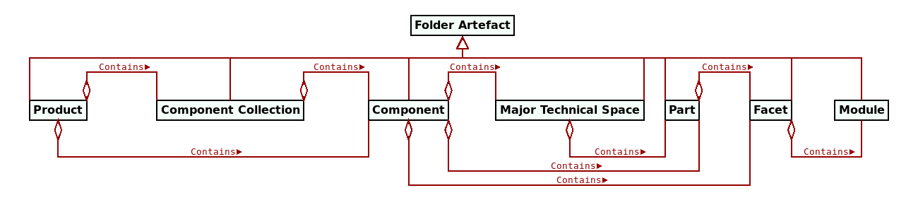
Figure 14: Simplified folder artefact taxonomy.
The first folder artefact of interest to MASD represents the software
product itself, and it is expected to be the topmost of the hierarchy —
typically, the root in a version controlled repository. A product, from
MASD's physical viewpoint, is a named and versioned artefact
hierarchy evolving over time. Products are ensembles of
components45, and these can have zero or more
TS-specific targets — e.g., executables, shared libraries,
PDFs and the like. Typically, each
component is associated with one major TS, but multiple major
TSs are also supported, catering for more exotic
topologies.46 For brevity, components with a single major
TS can elide the TS folder via non-structural variability.
Components within the ensemble can also form cohesive sub-groups called
component collections; where the component collection is made up of a single
component, the component collection folder may be elided.
Whilst Lakos' work is of great significance to our own, we nevertheless disagreed with some of his choices on terminology. For example, Lakos couples components with the C++ TS, defining these as an amalgamation of header and implementation files. This was not a useful definition from a MASD perspective, given our quest to find TS-agnostic entities, so it required redefinition. More generally, Lakos work is best seen as inspirational to our analysis rather than its literal substrate.
This additional complexity is required in order to support
components with implementations in multiple programming languages. It is of
particular relevance in the context of tools such as SWIG
(Marco Craveiro, 2021a) (Section 5.3).
To be clear, the folder artefact representing the C++
TS is always called cpp within the physical domain, as this is an
intrinsic property of the entity. However, the MT chain that transforms
the folder artefact into a folder takes non-structural variability into
account, allowing users to override the folder's name.
MASD's use of colour is inspired on Coad et el.'s work (Coad, Peter and Luca, Jeff de and Lefebvre, Eric, 1999), though heavily customised for its purposes. Coad et el. put forward a compelling argument for the use of colour in UML diagrams, stating (emphasis theirs): "Color gives us a way to encode additional layers of information. The wise use of color increases the amount of content we can express." (Coad, Peter and Luca, Jeff de and Lefebvre, Eric, 1999) (p. 6) Their analysis rests on the shoulders of Tufte (Tufte, Edward R and Goeler, Nora Hillman and Benson, Richard, 1990), but it goes further by performing a thorough analysis of the types of logical entities found in domain models. Part of MASD future work is to reconcile their approach with the physical and logical entities we have identified.
At present, MASD makes use of an ad-hoc palette for its metamodel elements. A review of the literature on the use of colour is needed, including material such as Waskom's interesting work (Waskom, Michael L, 2021), so that solid foundations can be laid in this regard.
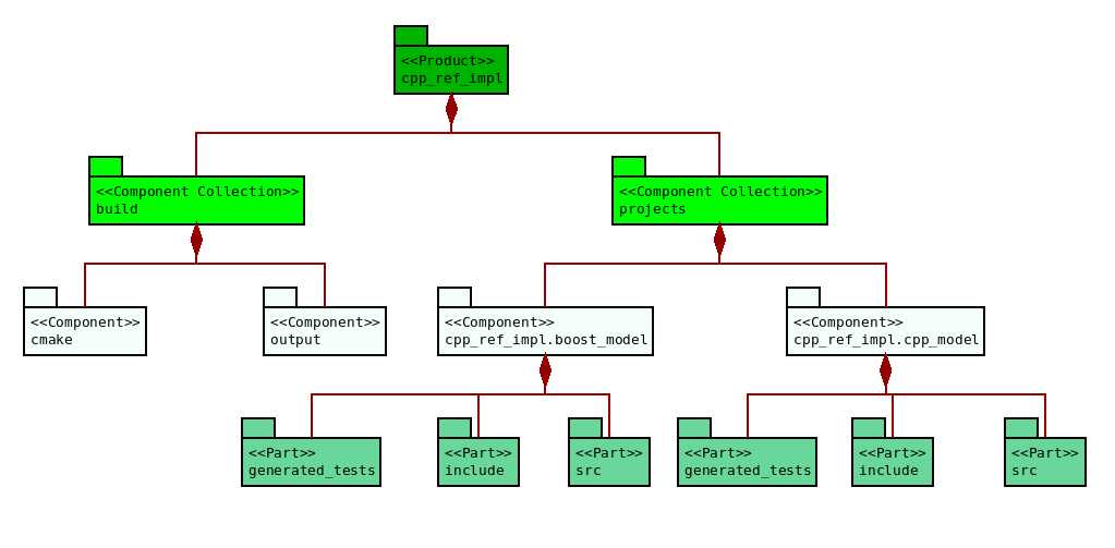
Figure 17: Sample top-level folders in cpp_ref_impl.
At the top we have the product folder artefact, cpp_ref_impl, with two
visible component collections: build and projects. Build contains an
assortment of files related to the build process such as CMake50
modules (cmake component), as well as the output component, dealing with the
artefacts created by the build system. The main source code for the product
lives under the projects component collection, of which two components are
shown: cpp_ref_impl.boost_model and cpp_ref_impl.compressed. Prefixing a
component name with the
product name is a configuration choice which can be disabled via
non-structural variability. Both components have the same internal structure,
with C++ as the single major TS, and the TS folder suppressed
by non-structural variability; and both have three parts on show:
generated_tests, housing all code-generated test code, include, with all
header files for public inclusion, and src, with the implementation files.
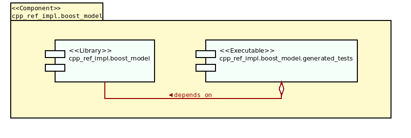
Figure 18: Targets in a sample Component.
The association between targets and components is not shown in the previous
diagram but, for completeness, it is displayed in Figure
18. Both components have two targets: an
executable target — responsible for making the generated_tests executable,
which is associated with the generated_tests part and runs all
code-generated tests — and a library target, associated
with the src part. However, it is important to note that targets are not
directly related to folder artefacts in the MASD domain architecture,
and MASD is not interested in the targets themselves; instead, they are
seen as by-products of build file state.
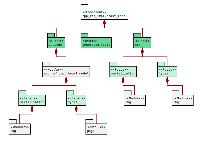
Figure 19: Folder artefacts in the Boost component.
The next example zooms in on component cpp_ref_impl.boost_model, allowing us
to see a selection of facets and modules (Figure 19). As
with the previous figure, three parts are shown: generated_tests, include
and src. The include part has a top-most module named after the
component itself (cpp_ref_impl.boost_model).
This module is known as the component module because it is used by C++ to
create distinctive include paths for header files, as we shall see
momentarily. The diagram displays two of the available facets: types,
containing type definitions, and serialization, containing support for the
Boost serialisation library. Each facet contains the module pkg1, a
user-defined namespace in the C++ TS.
These elements can now be put together to form an example include directive
for a file called entity.hpp, defined in the types facet and the pkg1
module (Figure 20). The
include path within the directive is regular, being a function of both MASD's physical
topology and structural variability.
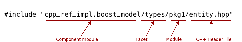
Figure 20: Example of a regular include path.
Our third example focuses on the Language Agnostic Model or LAM, which
exercises PIM support. This component is designed to export
the same generated code to two TSs, C++
and C#. As shown on Figure 19, each TS is stored on
its own folder, named cpp and cs respectively. The internal structure of
each TS is as per previous examples — with parts, facets and the
like — and thus omitted from the picture.
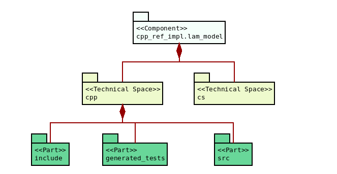
Figure 21: Folders in the LAM component.
The fourth and final example is a snapshot from the C# reference product
CSharpRefImpl (Figure 22). Whilst conceptually simpler
than the examples covered thus far due to having a single part in each
component, this TS
is not without its challenges. Marked in red in the picture is the component
with the generated tests for the main component CSharpRefImpl.CSharpModel. It
is so because MASD does not yet support a topology where the generated
tests can be placed outside the main component from whence they were
generated; at present, the notion of hierarchical composition of physical
entities is enforced strictly, so the same component cannot exist in more than
one place.51 Tests notwithstanding, the remainder of the
diagram is straightforward, with three facets being shown: types, with type
definitions, SequenceGenerators, for test data generation, and dumpers for
pretty-printing. Each of these facets has two modules — namespaces in the C#
TS: Package1 and Package2.
This issue is under active investigation at present, and will likely require minor changes to the domain architecture.
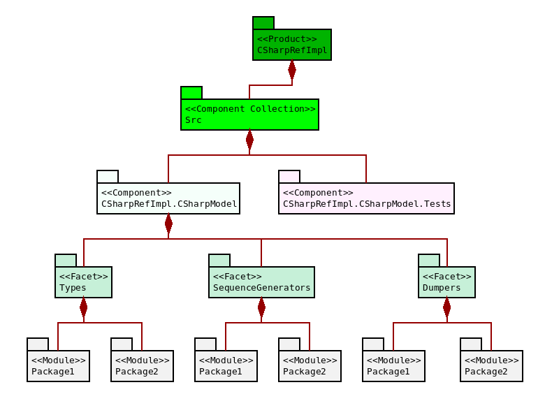
Figure 22: Folders in the C# Reference Product.
This example demonstrates the importance of covering multiple TSs in order to increase the range of variation within MASD's domain architecture. As further TSs are incorporated, the architecture will evolve to support those use cases, providing end users with additional flexibility. Moreover, non-obvious connections between TSs are also revealed, resulting in the unexpected emergence of features. For example, it is likely that the solution to support tests in a idiomatic manner in C# will enable additional use cases for all TSs.52
At present, all facets are combined into a single
library per component. This has sufficed so far, but does have its
inconveniences because you pay the full cost of a component regardless of the
features in use. If one could separate say serialisation from type definitions,
users of a component that do not require serialisation support would not have
to link against it. It seems plausible both external test generation and facet
splitting are related at a meta-level.
This example concludes our dissection of folders within MASD. Now that the main characters of the physical domain have been identified, they must be brought together into the methodology's metamodel architecture.
Cartridges were originally introduced in the context of MDA; there, the challenges with the term were also discussed. The notion, however, is generally applicable to any MDE-based methodology.
Examples of candidates for cartridges are the XSD tool and Protocol Buffers as well as other tools described in (Marco Craveiro, 2021a). These become cartridges once they have been modeled and integrated with MASD.
Cartridges are a good example of the power of integrating generation within a single framework. MASD initially added targets in build files to invoke ODB, with the tool invocation performed by the end user during the build process. By moving the ODB invocation into a T2T transform, we have opened the possibility of performing further processing on the generated files (via clang-format in this case).
In order to improve readability, constant width
font is used only for source code entities and vocabulary pertaining to the
logical domain. Physical space terms are depicted in regular font.
In the before-cited paper, Piefel and Neumann explain that (emphasis ours)
[…] the ultimate purpose of modelling is often code generation. While code can be generated from any model, we propose to use an intermediate model that is tailored to code generation instead. In order to be able to easily support different target languages, this model should be general enough; in order to support the whole process, the model has to contain behavioural as well as structural aspects. (Piefel, Michael and Neumann, Toby, 2006)
The analysis also raises the question of where to place the boundary between logical and physical domains. For Lakos, there is a stark distinction between the two: files and directories are part of the physical domain, classes and other TS constructs belong to the logical domain. In MASD the split is not quite as clear because we view file morphology and taxonomy as part of the physical domain; therefore some of what Lakos places in the logical domain is understood to be in the physical domain from a MASD perspective. In addition, the role of the logical domain in MASD is to model the physical domain, which is a very different take on the matter when compared to Lakos, where these two domains are largely unconnected. The lack on rigour in determining these boundaries has not yet brought about challenges, so the subject remains a candidate for future work.
Please note that these packages form a snapshot of current state, since the LMM is expected to change as our understanding of the domain improves; new packages may be added, existing packages may be merged when deemed to have overlapping functionality, and so on. The LMM has changed considerably since its inception.
Within the LMM, we took the somewhat unfortunate decision of abbreviating non-structural variability to just variability. This is a decision that may be reviewed in the future to avoid confusion.
Unlike in previous diagrams, this figure employs colouring merely to facilitate the present explanation. Typical MASD models do not follow this colour scheme.
The names of these types are somewhat atypical, by
design. We sought to avoid terms which were either keywords in MRI's
implementation language (C++) or which were already well-known from other
popular TSs — the idea being that MASD's interpretation
may not necessarily map to their understanding on a given TS. It is for
this reason that names such as class, namespace, package and so on were
eschewed. The prefix meta was also explicitly avoided because it was felt to
be a noise word ({Kevlin Henney}, 2021), given that all the types within the
LMM are metatypes. Nonetheless, these policies may be reviewed in the
near future, particularly where greater clarity can be attained.
Some modern languages such as Nim ({Nim Project}, 2022) have built-in support for strong types. Nim calls these distinct types, defined as follows: "A distinct type is a new type derived from a base type that is incompatible with its base type. In particular, it is an essential property of a distinct type that it does not imply a subtype relation between it and its base type. Explicit type conversions from a distinct type to its base type and vice versa are allowed." ({Nim Project}, 2022a) Primitives highlight another advantage of the MASD approach, which is to cross-pollinate ideas across TSs.
Whilst GoF designed patterns are referenced often,
please note that MASD does not limit itself to this set of patterns. It
just so happens that there is abundant literature as well as implementations —
and therefore ready-made use cases for MASD to consume. However, the
expectation is that other kinds of patterns will follow. As an example, work has
begun on integrating dependency injection — a technique of inversion of
control that echoes the strategy pattern (p. 315).
Abrahams and Gurtovoy define C++ Concepts as follows (emphasis theirs): "A concept is a description of the requirements placed by a generic component on one or more of its arguments." (Abrahams, David and Gurtovoy, Aleksey, 2004) (p. 77) Similar notions exist on other TSs such as C#'s generics, though it seems to be particularly developed within C++.
As previously mentioned, the generation of constraints for concepts, as per C++ 20, is not yet supported.
Having intermediary types generated implicitly without
representation in the model was found to be detrimental to the modeling process.
This is because it is no longer possible to associate non-structural variability
with the implicit type. For example, visitors at present must always be named
CLASS_visitor, with CLASS being the name of the type annotated with
masd::visitable. Nor can one add other configurable features to the type —
for example, generate immutable visitation only, etc. The correct solution is
to force users to create the visitor type as a UML class with the
stereotype masd::visitor, and then, via tagged values, associate the visitor
with the visited base class. This approach will be implemented in the next
releases of the MRI.
As implied by this statement, MASD does not support inner classes at the logical model level — i.e. classes defined within classes, which would map to the LMM as objects defined within objects. These constructs are supported in many TSs such as C++ and C#. Note that inner classes may be generated as part of the projection into physical space; however, their creation cannot be arbitrarily driven by structural variability. As typical in MASD, this feature will only be supported when there are well-defined use cases for their implementation.
The sub-typing of modules with regards to ownership at a
logical level may appear counter-intuitive, given that all of these three types
of modules ultimately represent containment. MASD does so because we
often treat these groupings separately. For example, product modules are at
times necessary — when creating include paths for instance — but in other
cases omitted. In addition, both product and component modules are combined
using dot notation when creating folders rather than creating one folder per
module. Clearly these entities are treated specially when compared to "regular"
modules, justifying the distinction. Furthermore, these different types of
modules are also projected to distinct physical elements (the Physical Domain section).
For historical reasons, product modules are currently
named external modules and component modules are named model modules in
the MRI. These legacy names are part of the evolution of the
understanding of the domain architecture, since the purpose of these modules
wasn't obvious initially. The MRI will be corrected to match the
description here presented.
Composite product names are useful to denote product
families, e.g. Famly.Product. Composite component names allow creating
groups of components within a product, e.g. ComponentGroup.Component.
As previously mentioned, this is expected to change in the near future with the addition of C++ concept constraints. The C# TS also has a notion of constraints, but as these are more limited, the mapping to object templates will require additional analysis.
From the perspective of the domain architecture, the codec representation is merely an implementation detail and as such we will not spend a lot of time describing it. The MASD Reference Implementation chapter will provide implementation-level details in this regard.
Chapter 6 of (Marco Craveiro, 2021) summarises our incursion into variability, and introduces, at a high level, all concepts used by MASD in the variability domain.
This entailed, for instance, making a clear distinction between structural and non-structural variability, with input variability taken to mean the superset of both kinds; and using variability, in isolation, when referencing the entire field of variability modeling within software engineering.
Structural variability is modeled in the logical domain, whereas generational variability is deployed mainly within the physical domain. Non-structural variability is dealt with in isolation because it was shown to be self-contained; as we shall see, once modeled, the variability domain is then superimposed over the logical and physical domains.
Please note that this is a simplification; MASD does not require the use of UML per se, as we shall soon see. Historically, however, the majority of MASD's modeling was done using UML class diagrams, and they will remain a first class citizen. In addition, any other representation supported by MASD must be isomorphic to the entities in UML class diagrams.
Bindings are deficient at present, in that they do not
support referring to specific elements in the LMM. For example, the
correct binding for the enumerator feature bundle should have been
masd::enumerator, given that this is the only metatype in the LMM
that can make use of this feature. In the future, the address of the logical
elements will be used for the binding.
The matter is best understood via an example. Given two types A
and B, where type A has a member variable of type B; if type A enables
certain regions of physical space — for example the hash and serialization
facets — then this implies that these regions must also be enabled on type B
in order to create a valid configuration. Solving, via methods such as
BDDs (Czarnecki, Krzysztof and Wasowski, Andrzej, 2007) or SAT (Batory, Don, 2005), will
allow the automated resolution of these dependencies. This is an area of future
work.
The name profile is unfortunate because it is easily
conflated with the notion of "UML profile". Presently, there is ongoing
analysis to determine a better name for this concept.
The rules defining the application of multiple profiles
are, at present, deceptively straightforward: each profile is applied, in
turn, in the order defined by the binding. However, there are clear
limitations with this approach such as the definition of conflicting
configurations (e.g. enabling feature A in profile P0 and disabling
feature A in profile P1). As with solving for valid configurations, an
element of upfront validation is required to, at a minimum, alert users to
potential conflicts.